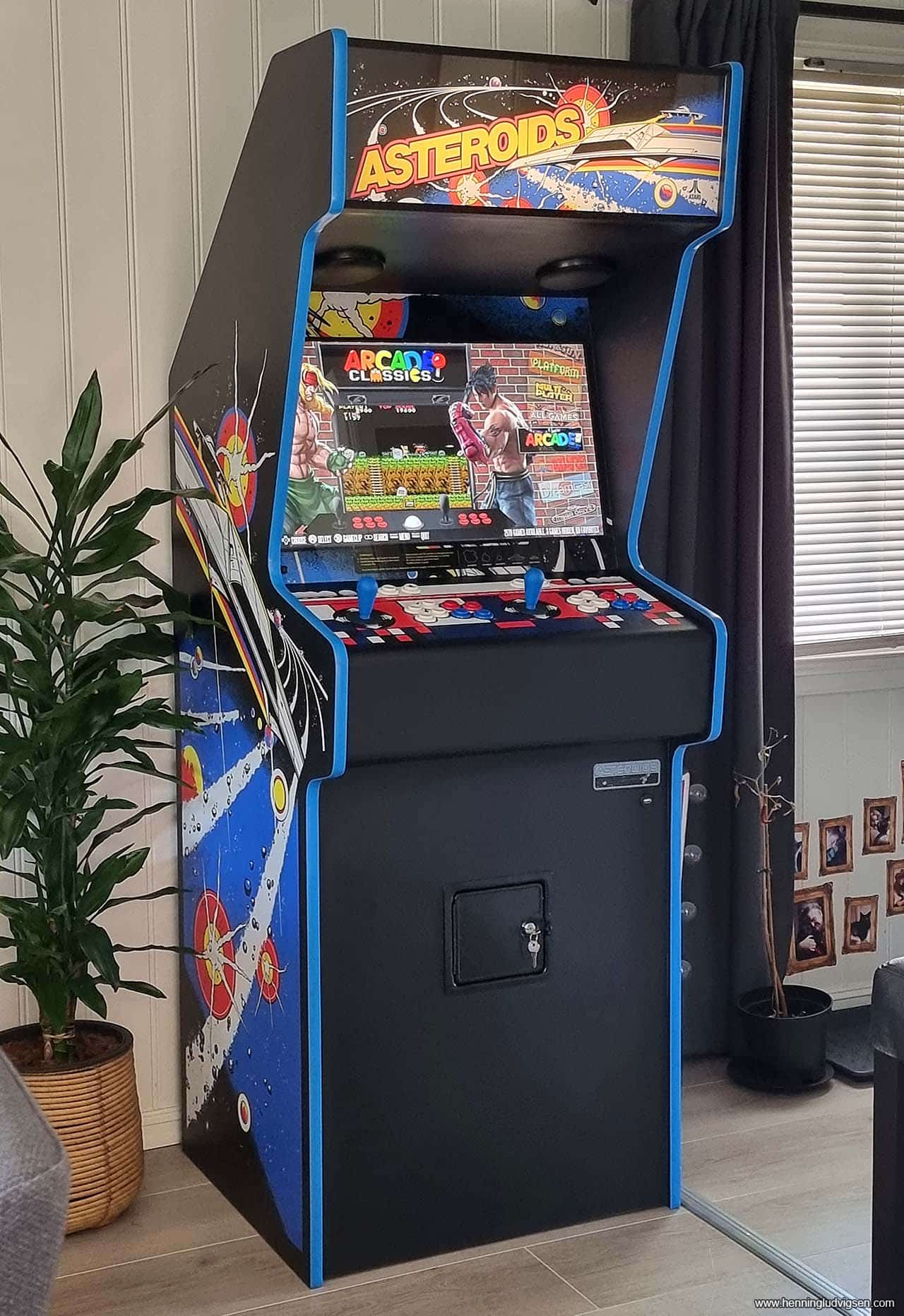
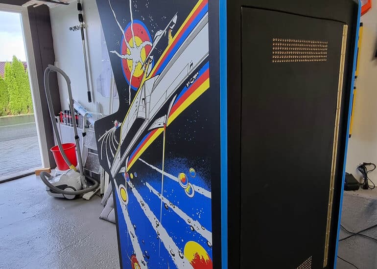
I’ve always had a thing for the top heavy arcade cabinets of the late 70’s and early 80’s, and especially the Atari cabinets. So for a good while I wanted to make a replica of a large upright cabinet from that era. After considering a few of the classic arcade cabinets I decided to go for a 1979 Asteroids cabinet, as I really love the look and feel of it. For this build I'm using a Raspberry Pi 4, with a smaller but more testet game image with approximately 2800 games.
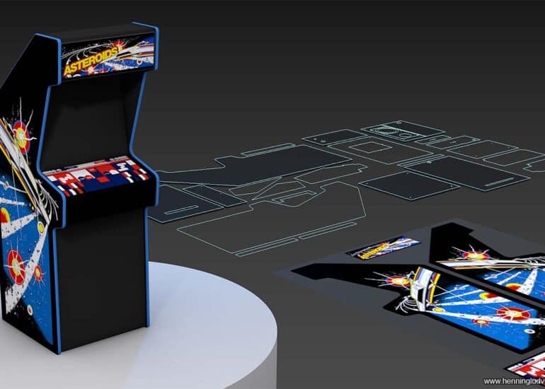
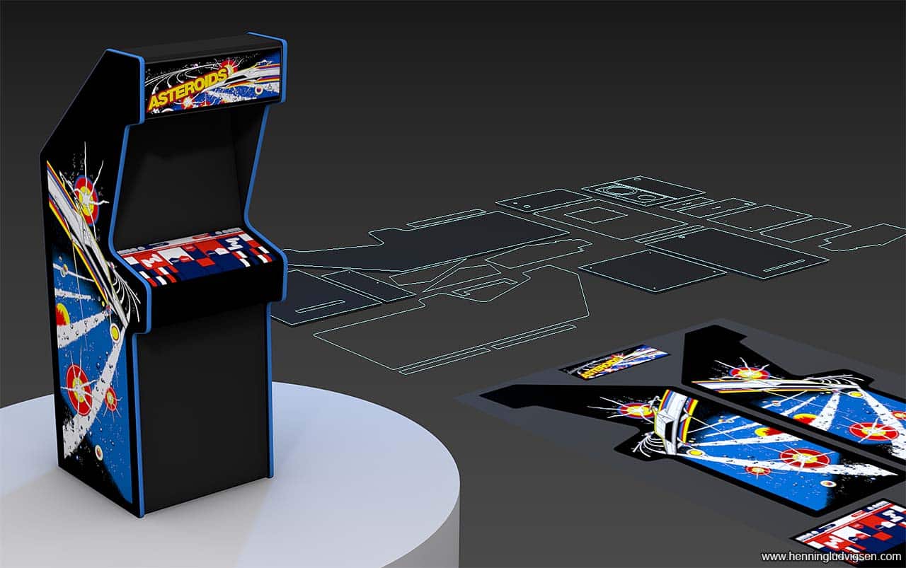
3D model and printed template
I managed to get ahold of the original blueprints of the cabinet and transferred this to my 3D software and modified it to fit my way of building it.
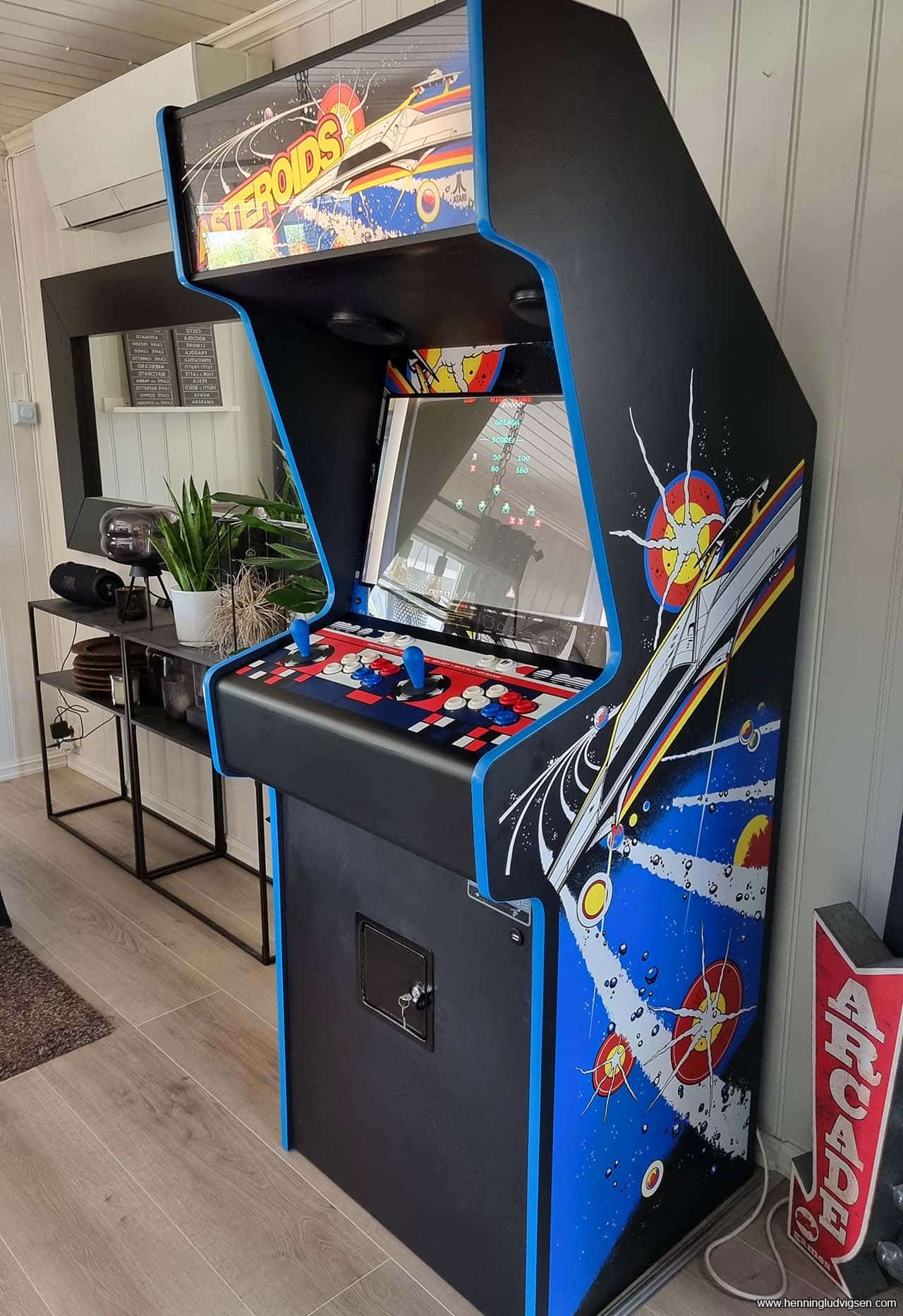
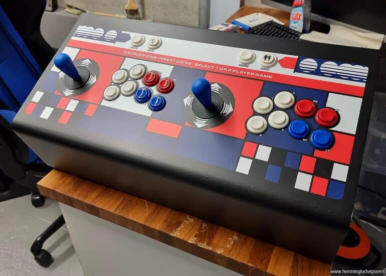
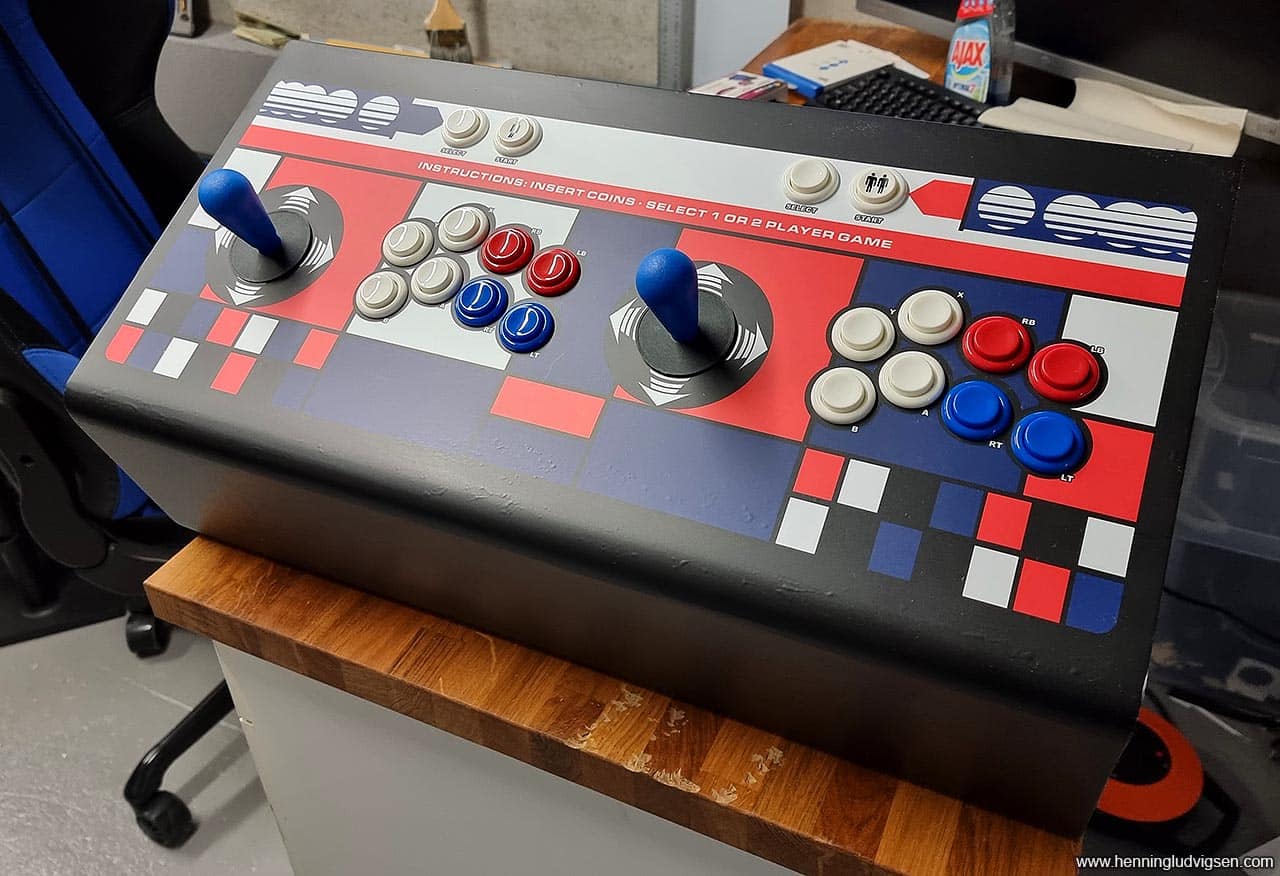
The original Asteroids cabinet has black T-molding, but I decided to modify it and go for blue. I just think it looks better than the original version. The control panel will obviously have to be different as I want this to be a multi game arcade for 2 players but I also wanted to make it as close as possible to the original, so I modified the control panel art to make space for all of the additional joysticks and buttons.
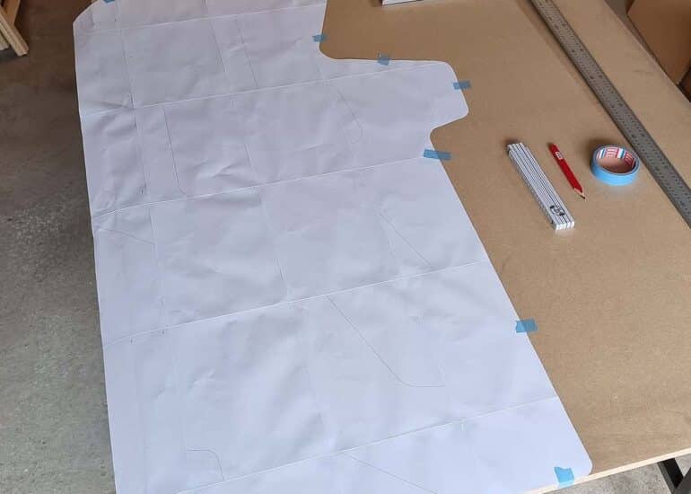
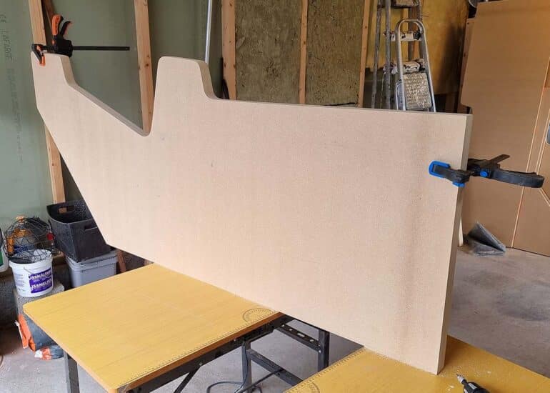
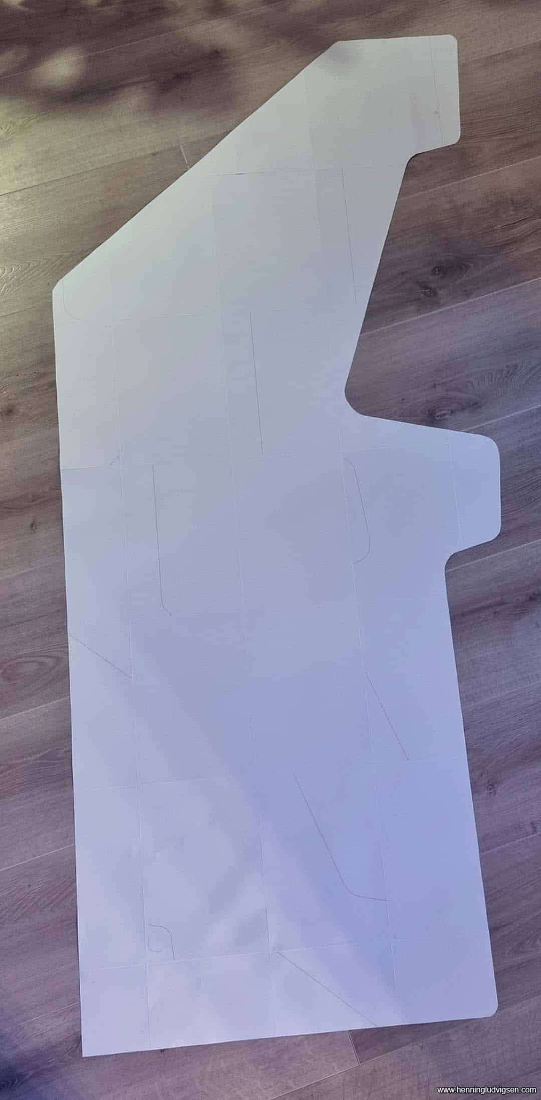
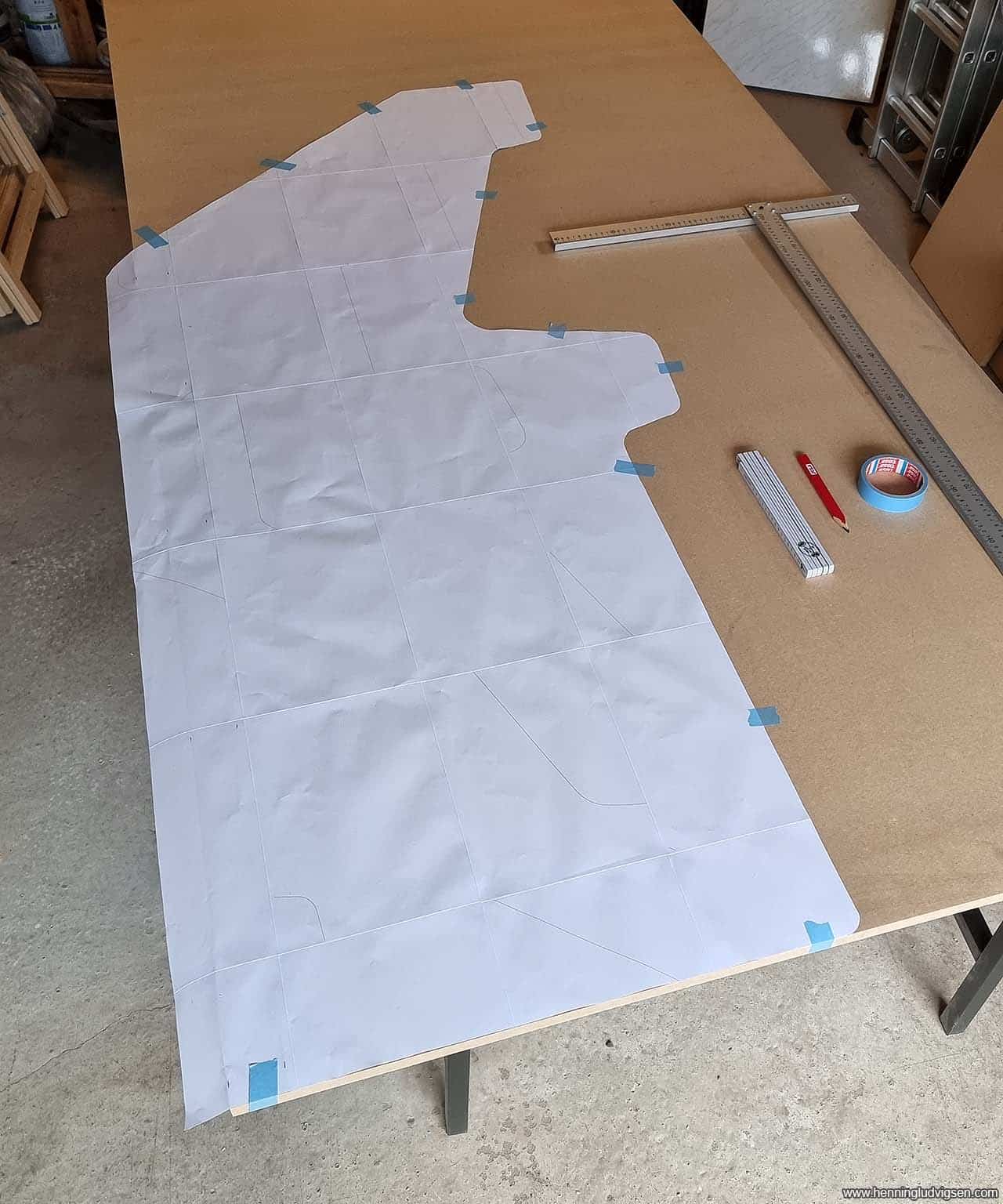
I converted the 3D blueprint to a 1:1 scale template by printing it out and scotch taping all the pieces together, and cutting it out with scissors.
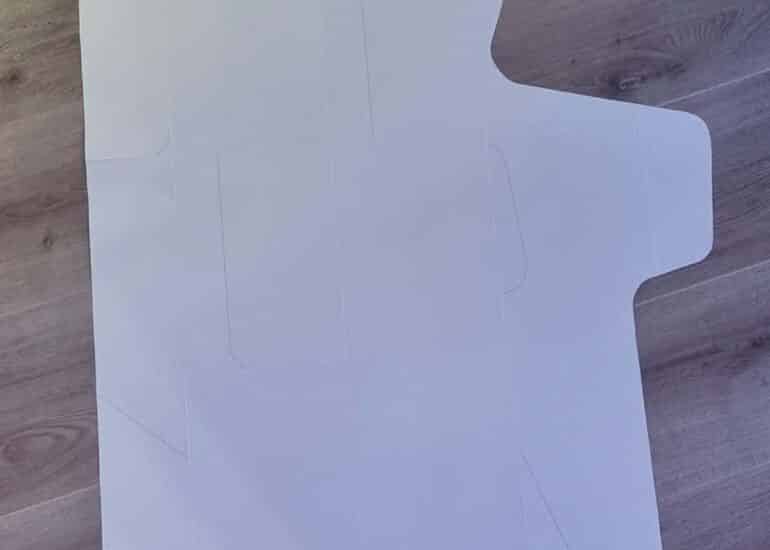
Next, I taped the template onto a 19mm MDF board but I decided to make the side panels more narrow by removing 5 cm of the back, as I wanted the cabinet to take up a bit less real estate but at the same time respect the original shape and feel.
Screen
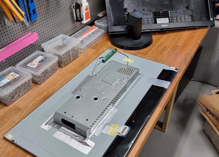
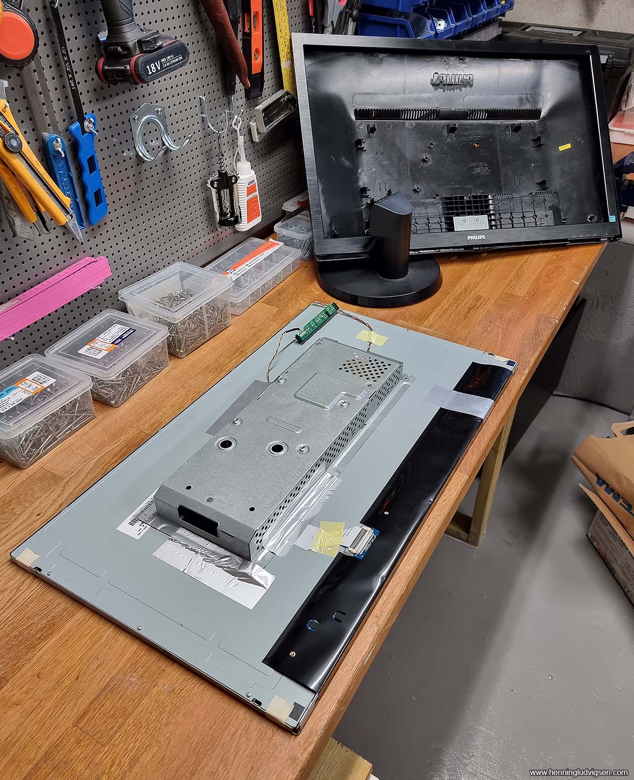
I got a nice looking 27» screen, and stripped it of the plastic panels. I glued the PCB with the control panel onto the back of the screen so that I can still access and use it if needed from the inside of the cabinet.
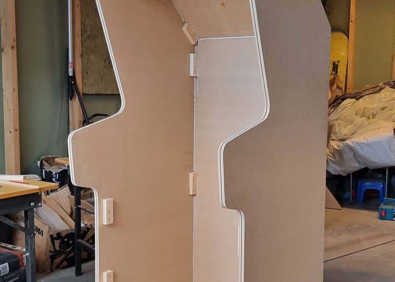
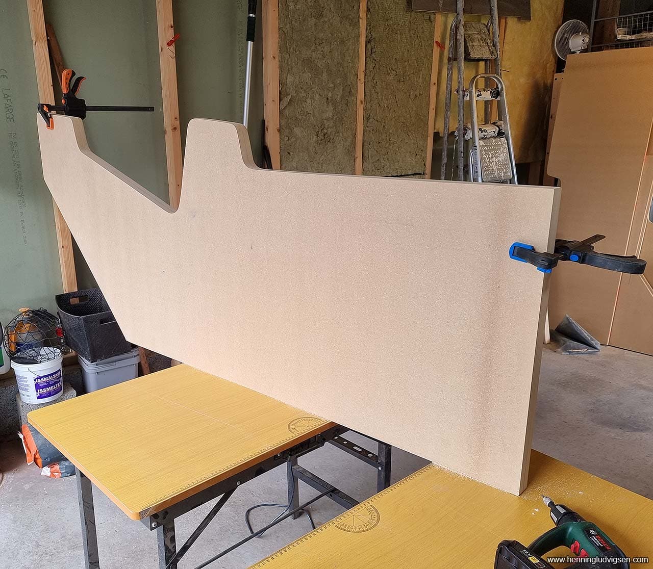
Cutting out the side panels
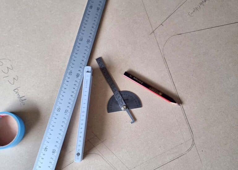
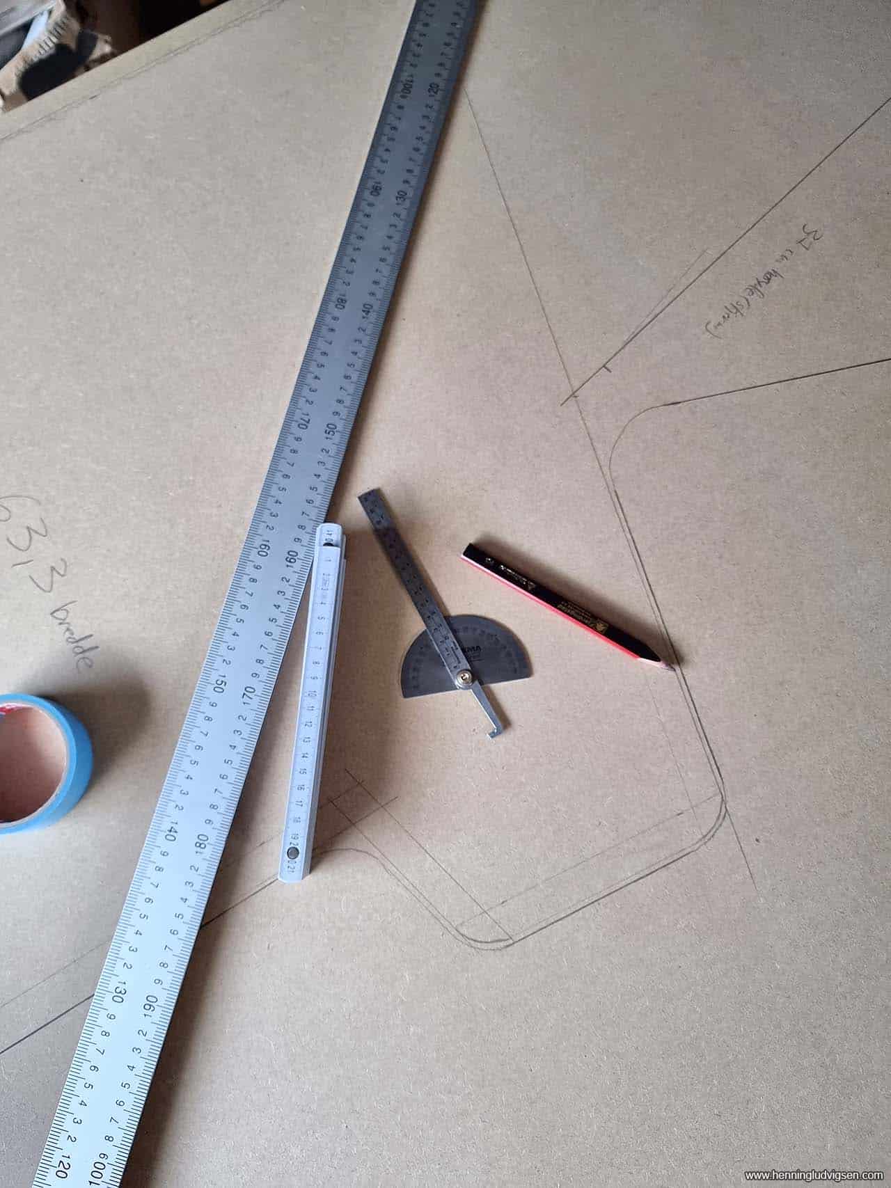
Next I traced the edges of the template on the MDF board, removed the template, and started sketching where the connecting pieces should go.
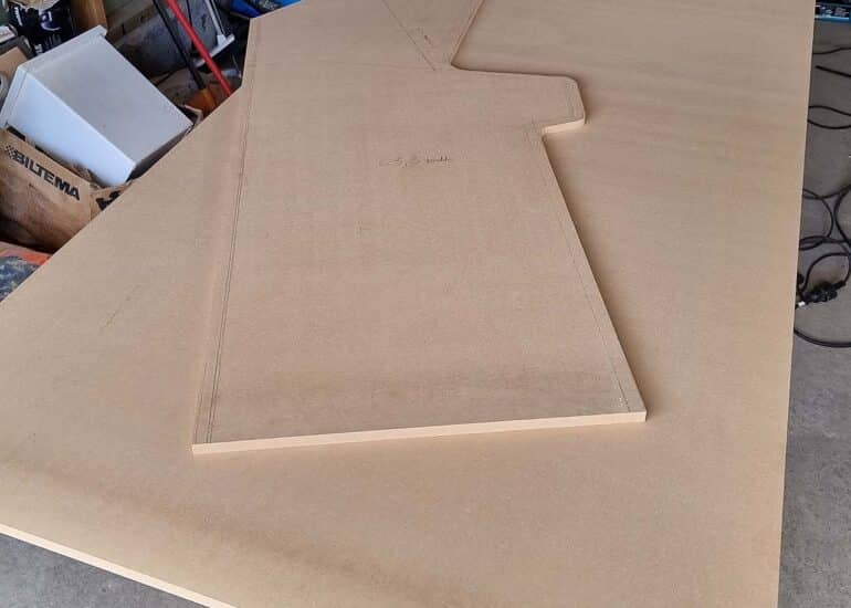
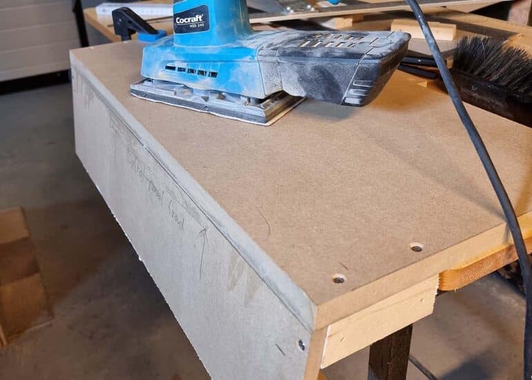
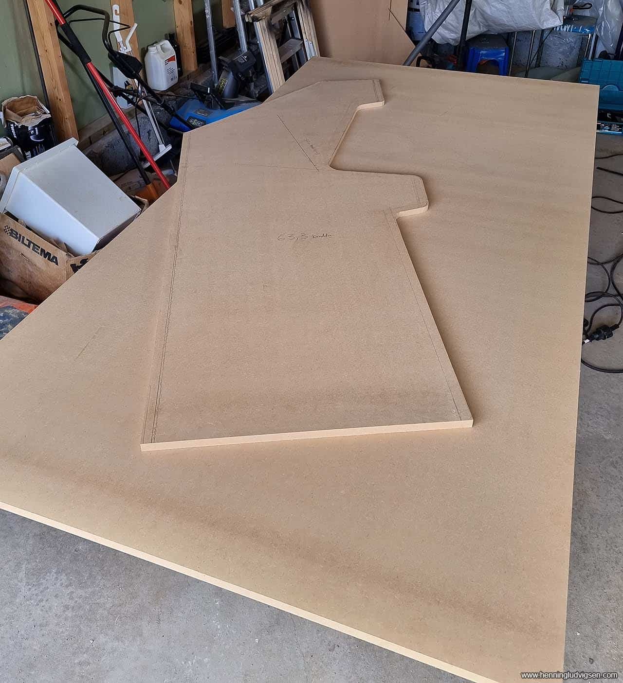
I cut out the side panel using a combination of a fine toothed circular saw (and mounted metal rules as a guide) for the straight areas, and a high quality jigsaw for the rounded parts. I used to have a low quality jigsaw that would bend and mess up the edges, but my new high quality one cuts all curves completely straight. Having high quality tools makes a world of difference!
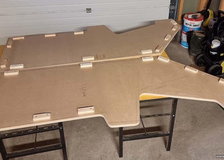
Then I traced the first side panel onto a second 19mm MDF panel, and cut it out. Then I clamped both side panels together and used a sander to make them completely identical. Please use a proper mask when doing stuff like this!
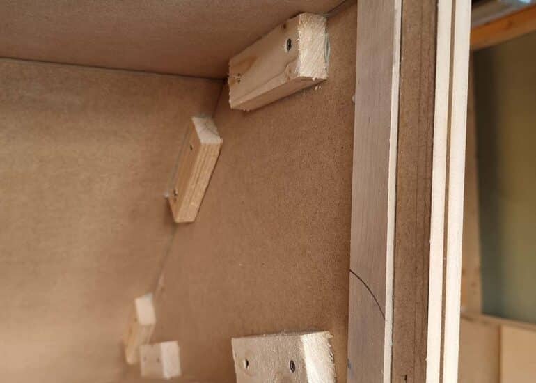
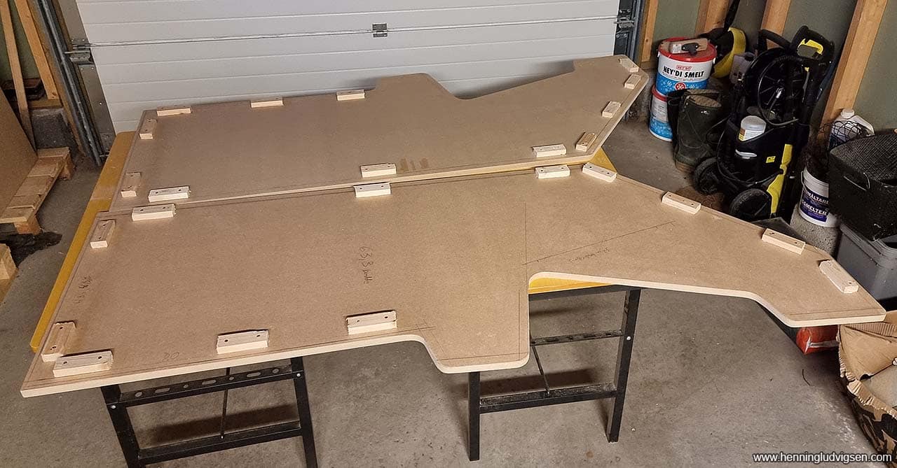
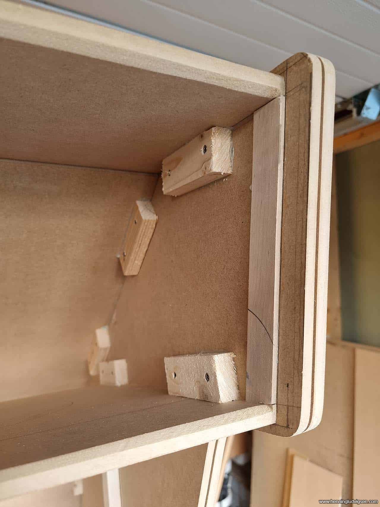
Adding connection pieces
After spending quite a bit of time mirroring all of the guidelines for the connecting pieces, I added the connecting pieces using wood glue and screws that are just long enough to not exit on the other side. I had to drill holes in the connecting pieces as they would split if not.
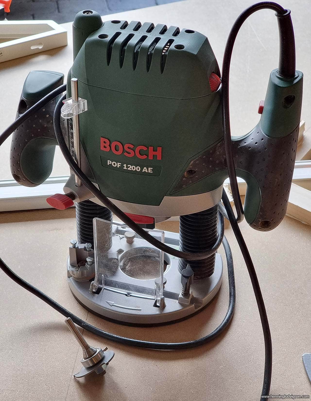
Routing T-molding slits
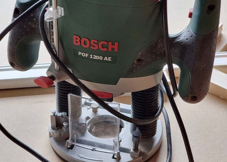
I used my router to cut the slit for the T-molding before starting any additional assembly. It’s really important to do this as early as possible.
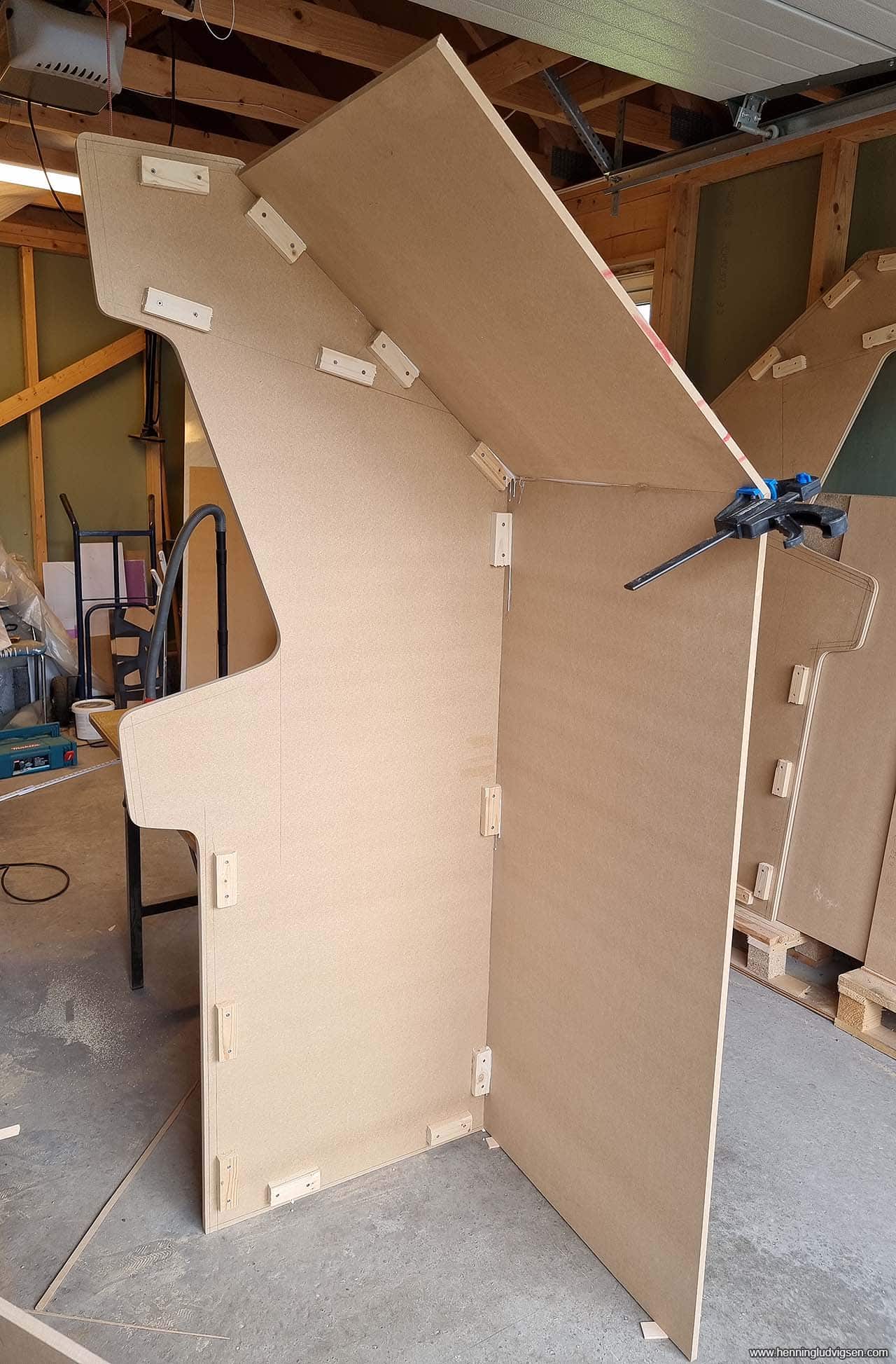
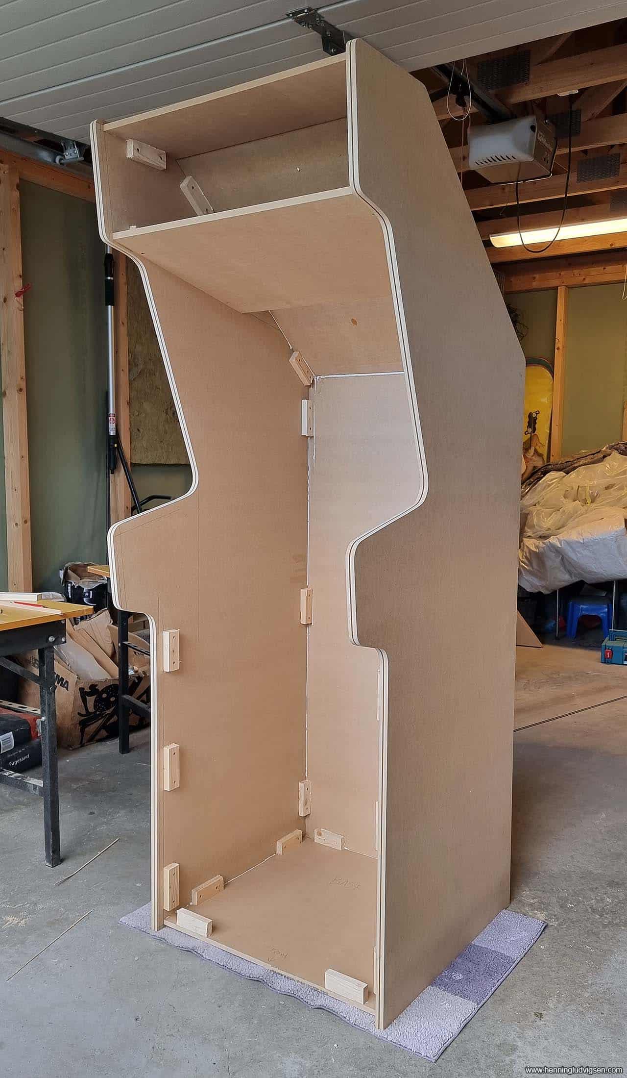
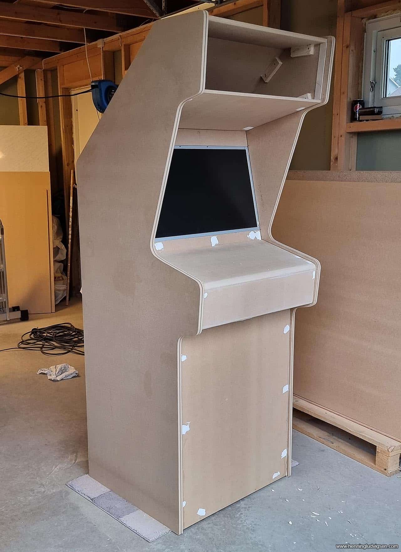
Assembly
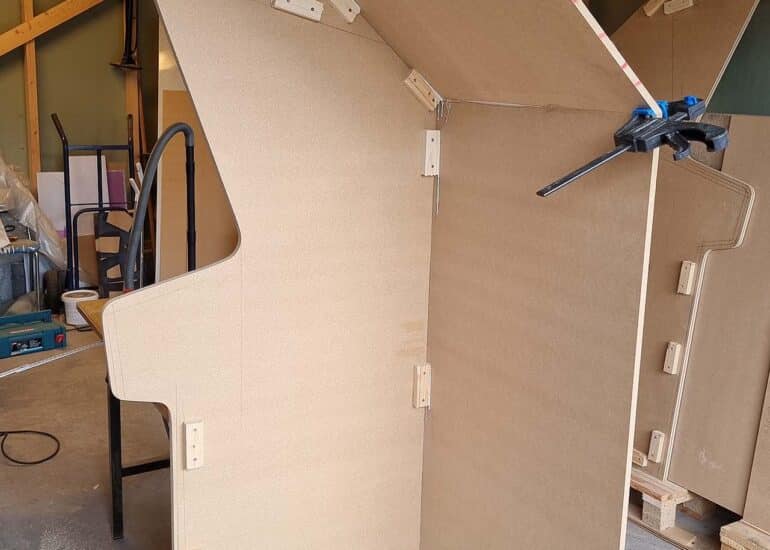
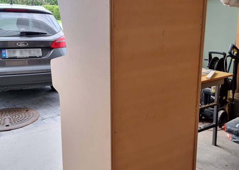
Next, I started adding the back panels using wood glue and holes. I had to pre drill all of the screw holes, and also use a screw sink drill bit to make sure that the screw heads would not stick out. The front and back panels are 11mm MDF, to reduce the full weight.
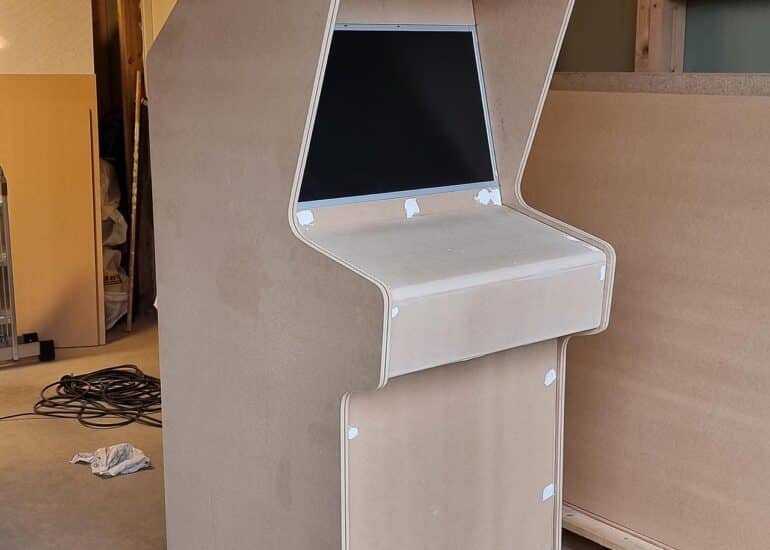
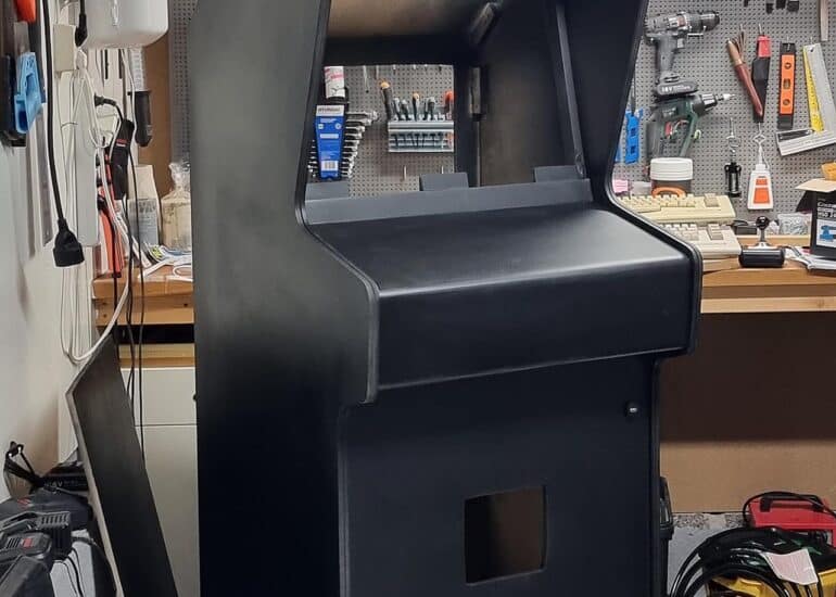
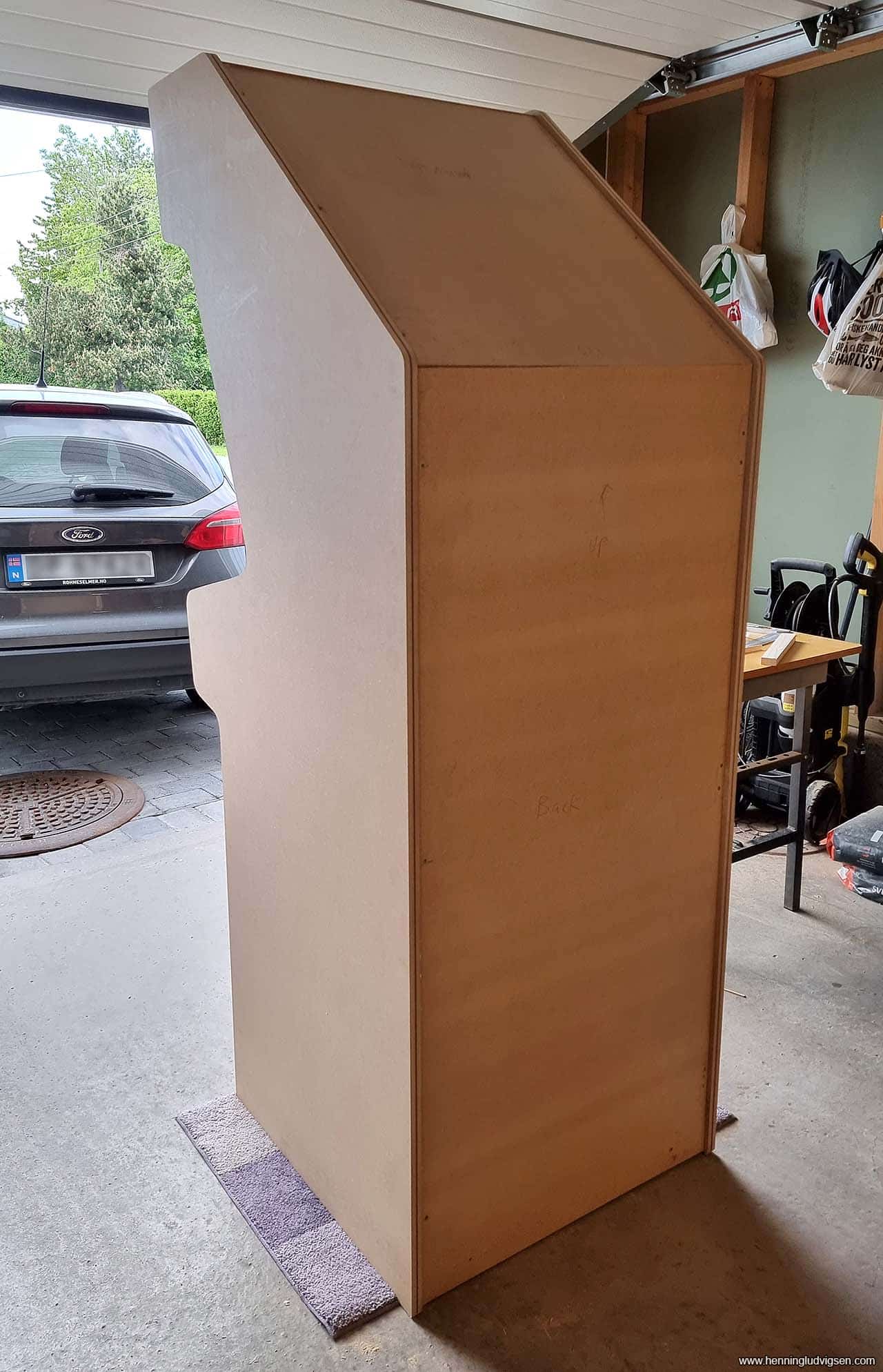
Cabinet is starting to shape up, and I added a small rug on the floor to protect the MDF from any damage.
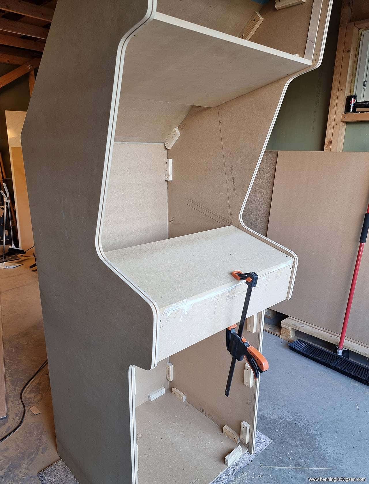
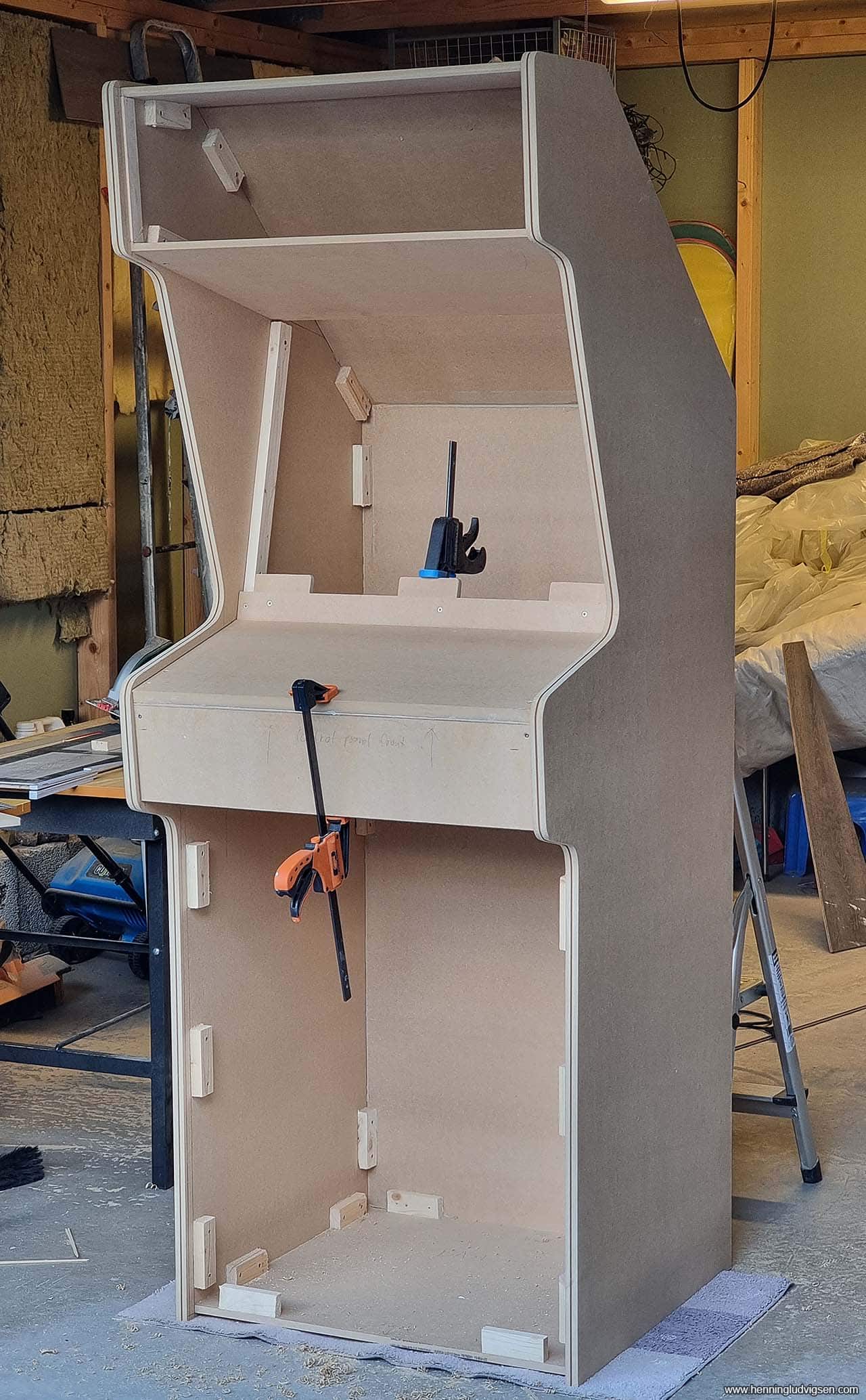
Control panel and screen area
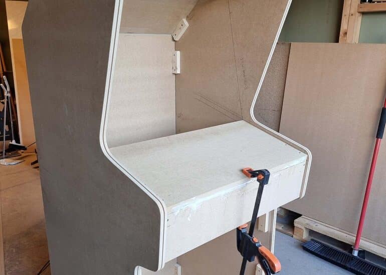
I wanted to make the control panel easily removable, so I mounted it in a way where it would fit perfectly by resting on the connection pieces, but only get glued and screwed within itself. Then I could remove it once mounted by simply removing 2 screws from below
I made sure the front and back pieces had the exact same width as the stripped LCD screen, and added some vertical resting lips. And 3 resting lips at the bottom.
Marquee light box preparations
I also added some thin wooden lists on each side of the marquee box to avoid any light bleed. I also chamfered the edge at the top and bottom of the inside of the marquee box to obstruct as little light as possible.
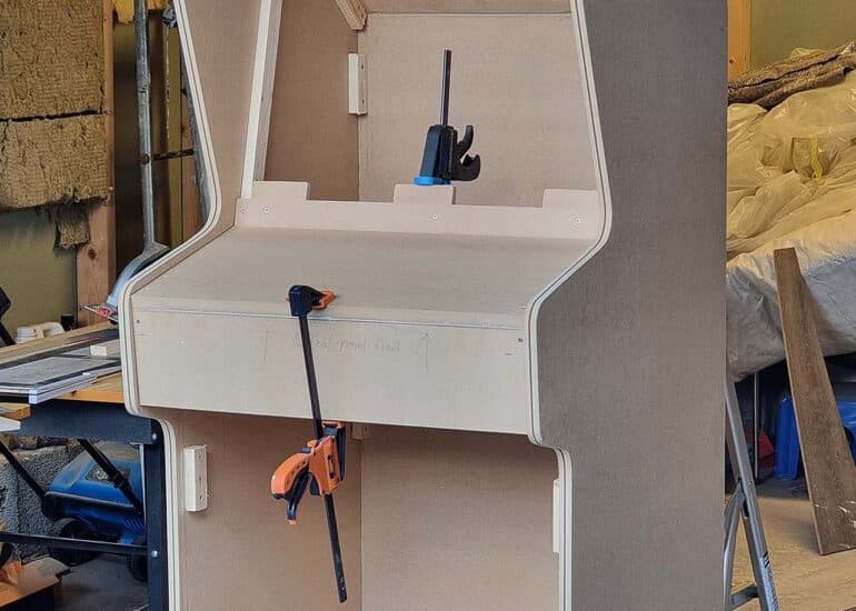
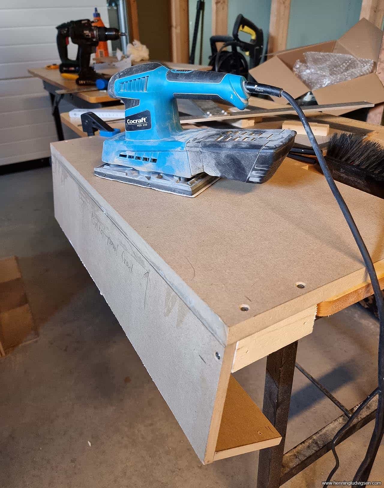
I removed the control panel and started carefully rounding the edges on the front and bottom using a sander.
Next I re-mounted the control panel, added the screen, and cut a piece of MDF that fits above the screen to nicely lock it in. I also added some putty in all of the screw holes.
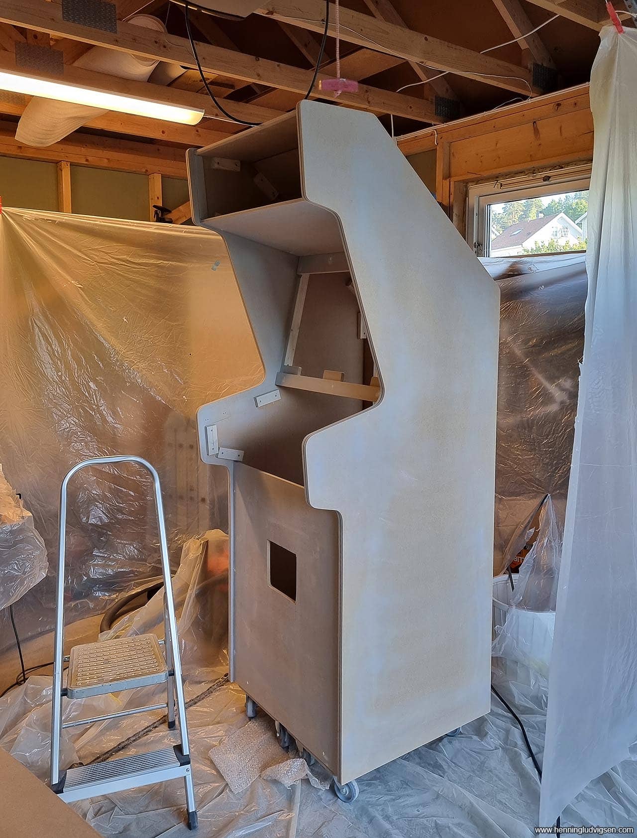
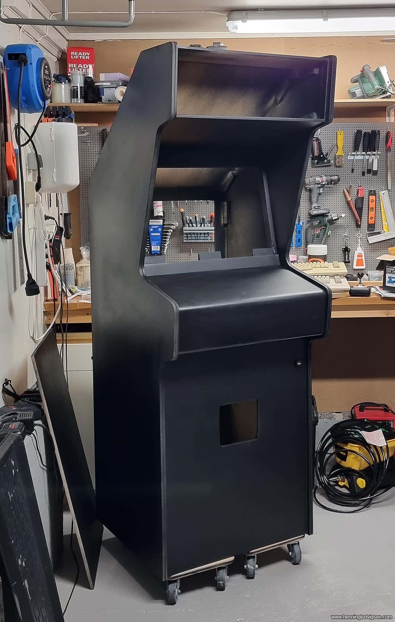
Primer and paint
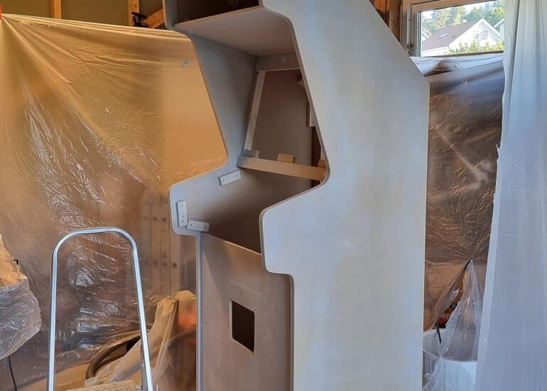
I sanded the entire cabinet and applied a layer of primer that I in turn sanded using finely grained sandpaper. I also cut a hole for the coin door.
After a few issues of painting the entire cabinet using a WAY overpowered spray machine, I had to sand it down a few times to get rid of any running paint and basically start the priming and painting process from start. But, after a few rounds I managed to resolve it and get a decent result.
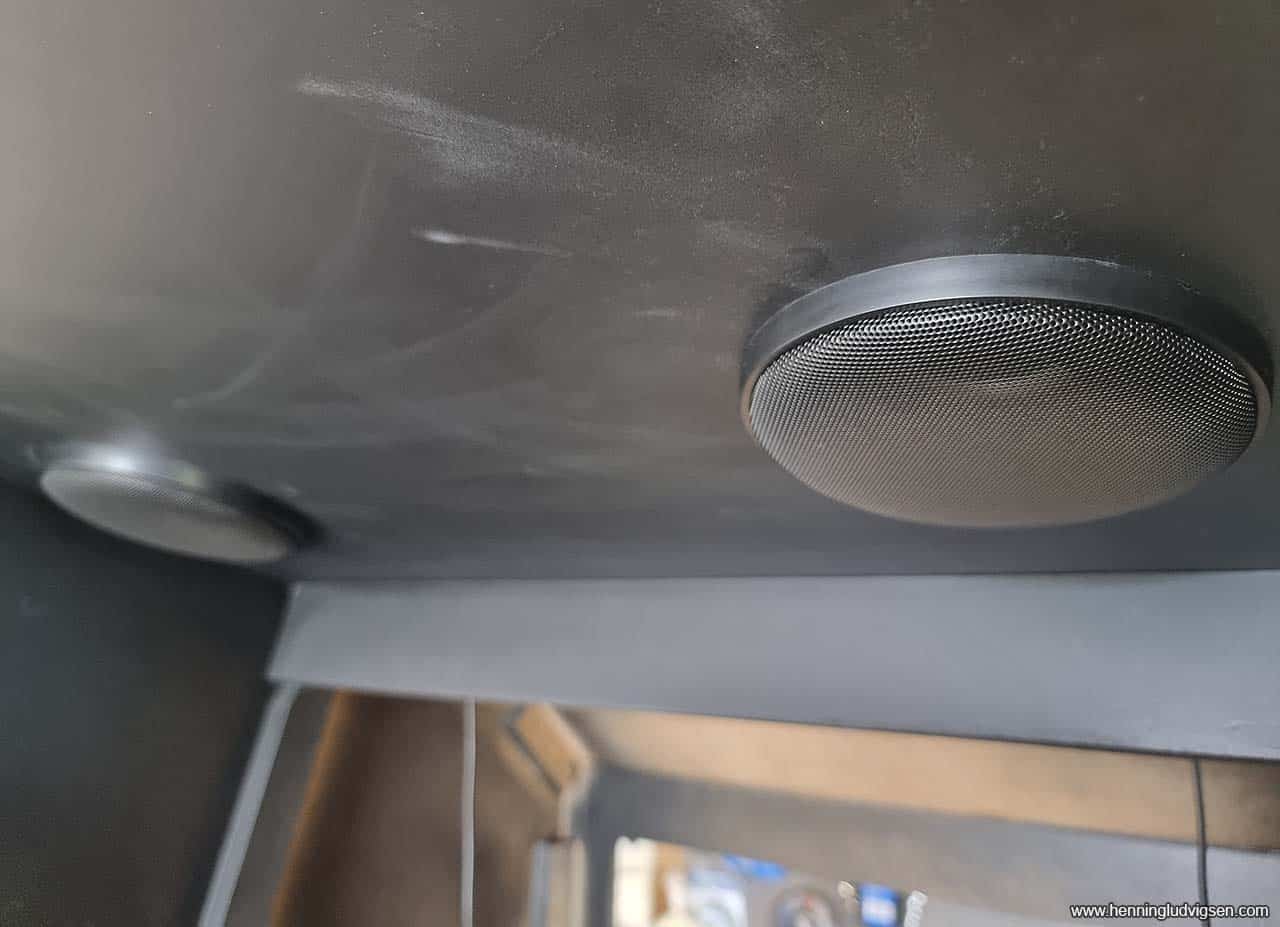
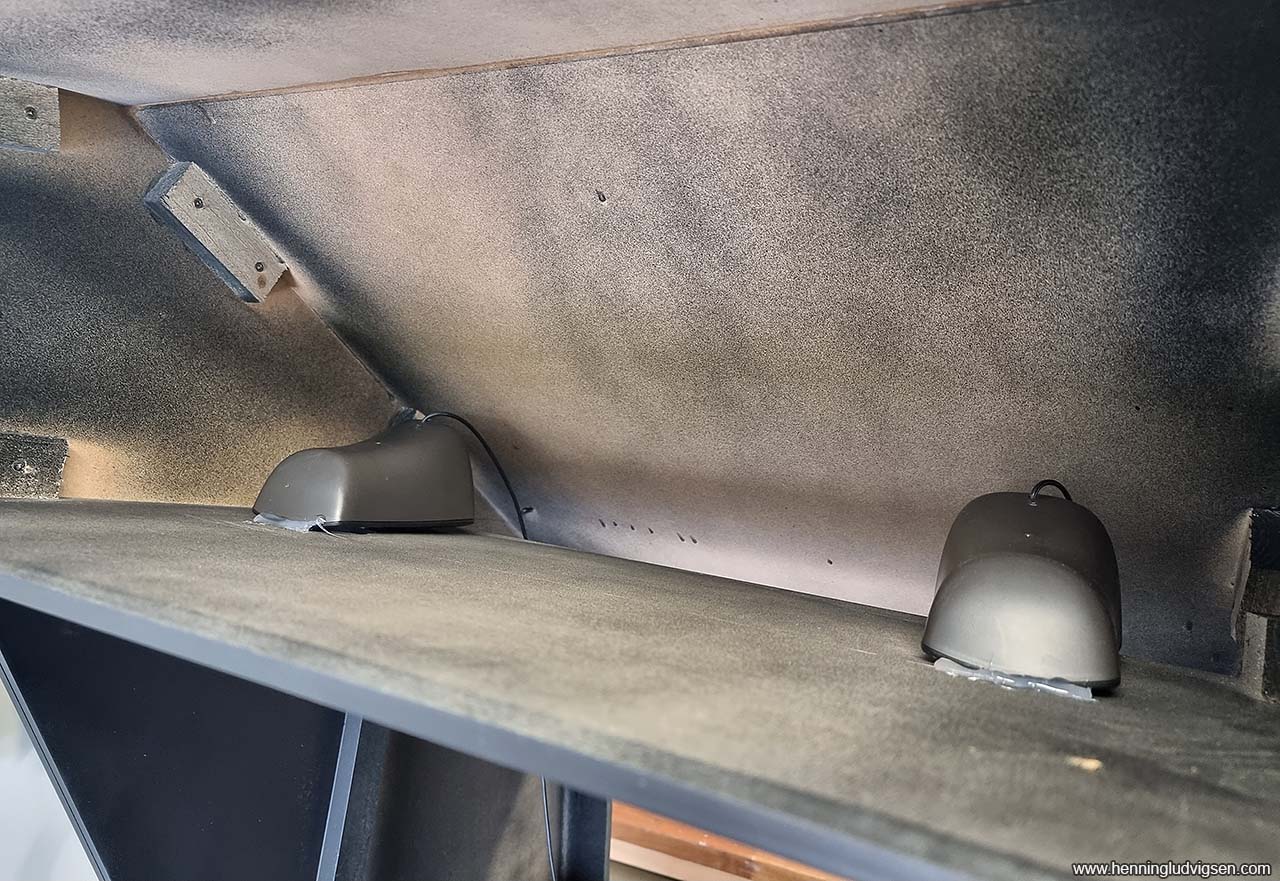
Speakers
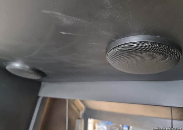
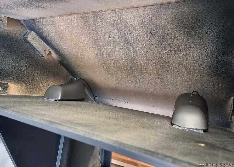
I drilled large holes for the speakers, painted the inside of the newly cut holes and mounted the speaker covers. I got some old PC speakers with a cheap subwoofer from a classified ad and simply hot glued them onto the speaker holes. The Subwoofer got fastened at the bottom of the cabinet for some added bass effect.
The handy thing with hot glue is that you can remove it fairly easily using a heat gun.
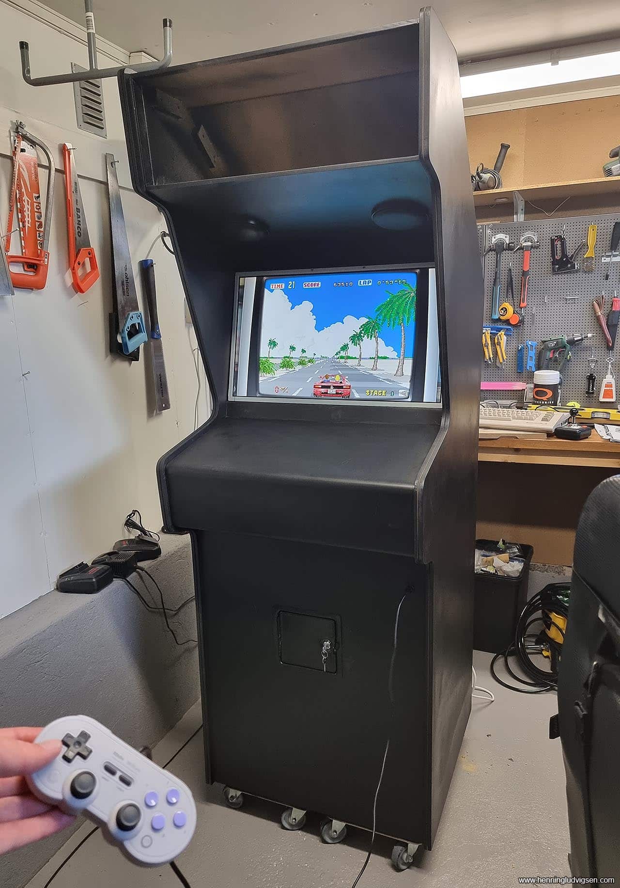
More assembly and testing
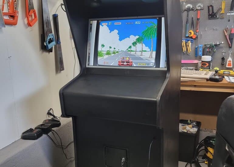
I mounted the coin door, drilled a hole for the USB connection (for games that play better using analog sticks, or if you want to have a 3rd player. I also added the screen, installed the Raspberry Pi 4, and gave it a test run.
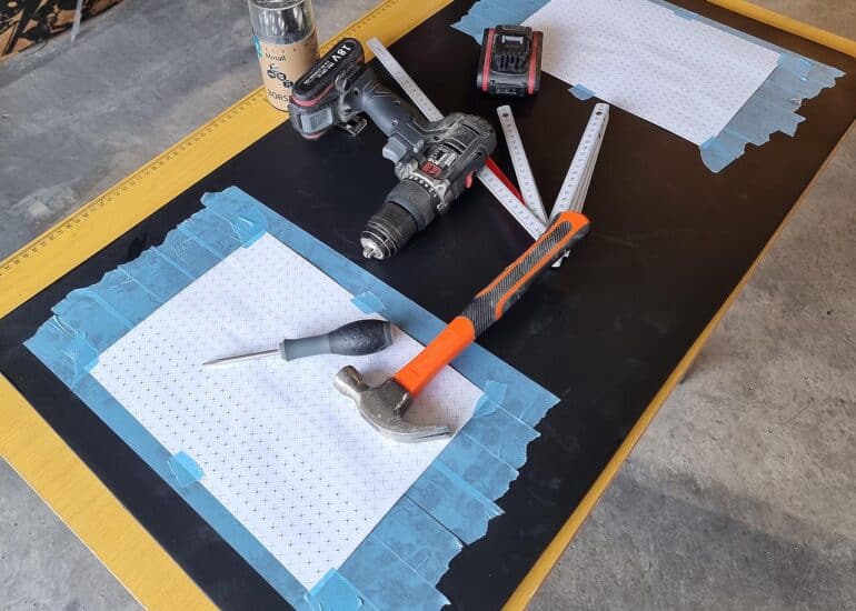
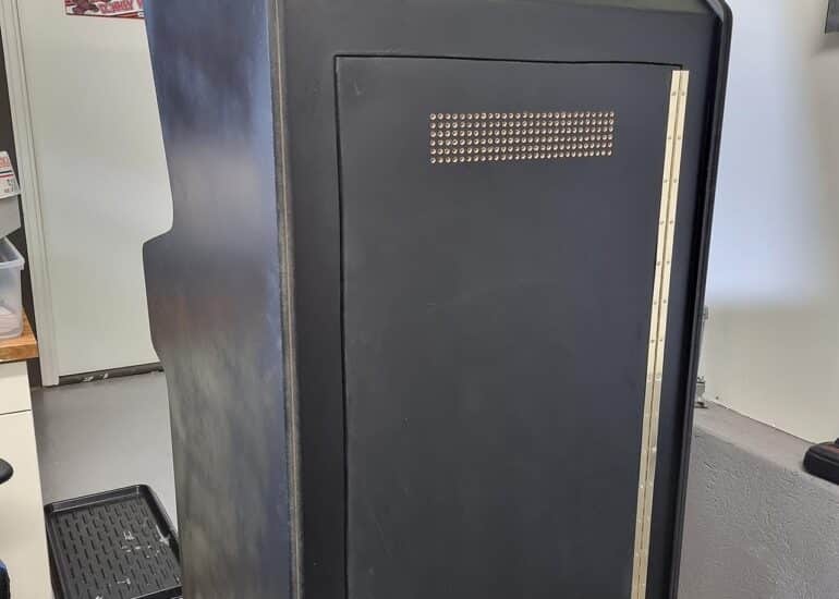
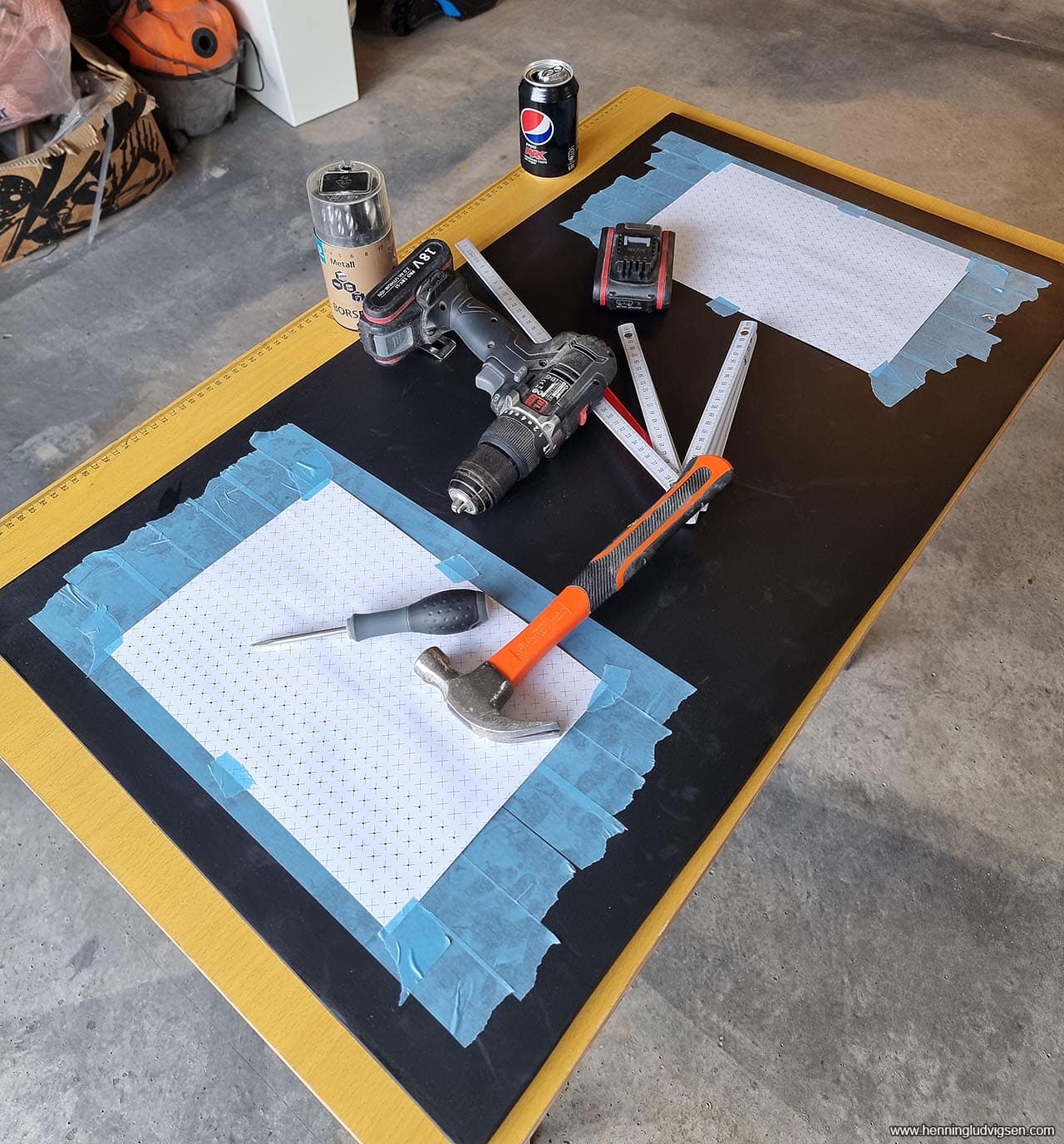
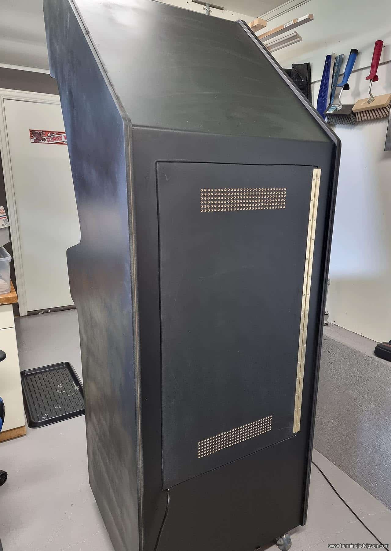
Inspection door ventillation
I needed an inspection door at the back of the cabinet, and also some ventilation. So, I printed out these evenly spaced grids that I taped on and used the awl to make small holes to guide the drill. At this moment of the process I had contracted Covid, but found great relief sweating things out making these ventilation holes. But, quite amazing how such a simple task can feel so hard when feeling very much under the weather.
I found a piano hinge that fit perfectly for the door. And, don’t mind that skewed cut at the top of the inspection door. I recommend cutting out inspection doors by properly sitting the entire cabinet down, using proper lighting and taking your time. Luckily not many will see it.
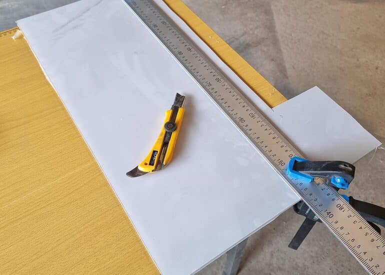
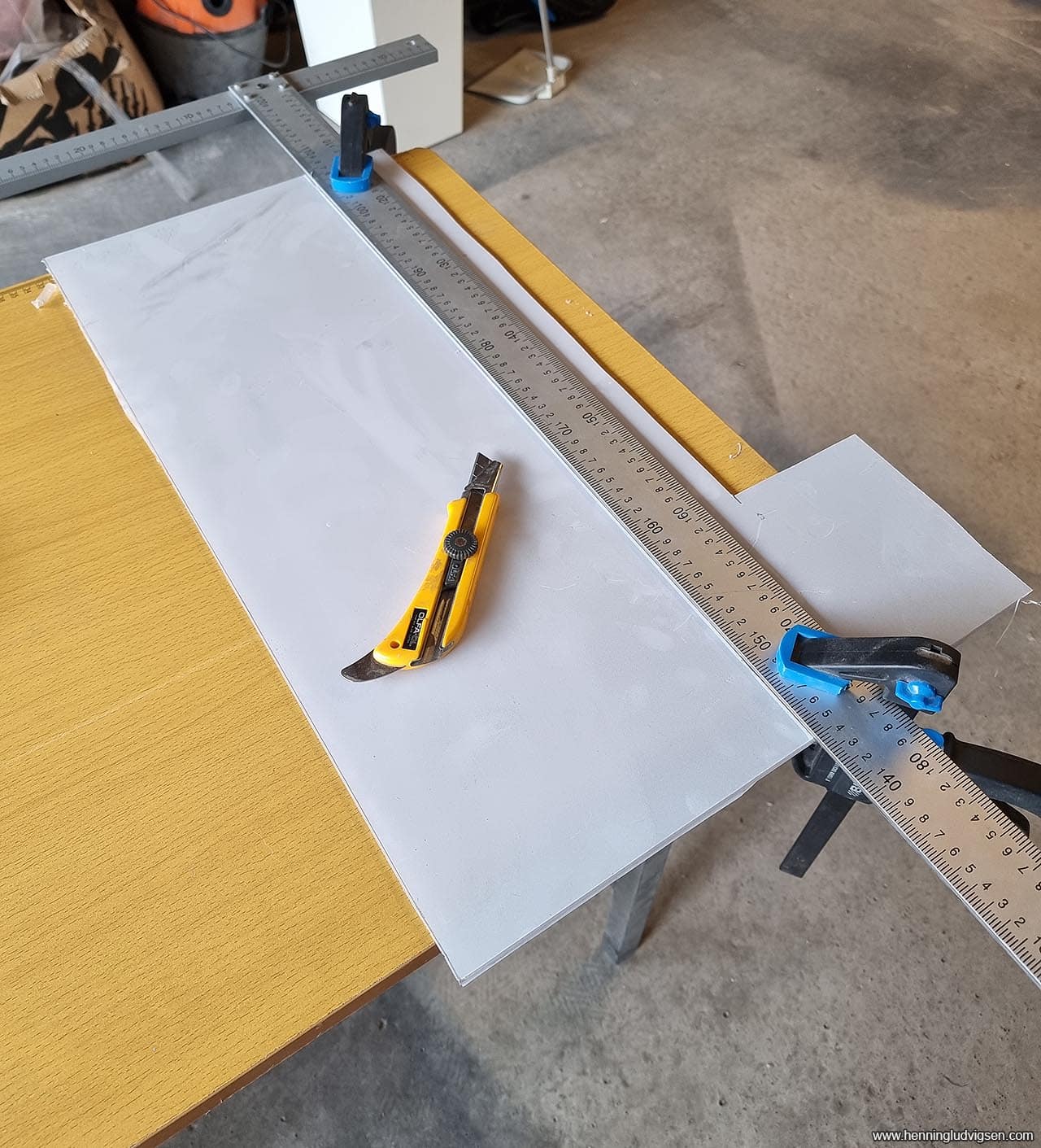
Plexiglass and marquee light
I started measuring the sizes needed for the plexi glass for the marquee and screen. I cut the plexi glass by mounting it down properly using clamps and a metal ruler, then cutting many, many times along the ruler using a stanley knife, before moving the plexi glass cut to the edge of the table, clamping it down again and simply breaking it off. If the cuts were done properly, it should break off along the cuts in a nice and clean way. Make sure that the piece you want is on the table, and the piece you break off is not being used.
I purchased a LED light that fit perfectly inside of the cabinet. Ideally I should have either painted the inside of the light box white, or added some kind of foil to reflect it, but I decided to try without to avoid getting the light too intense in the final version.
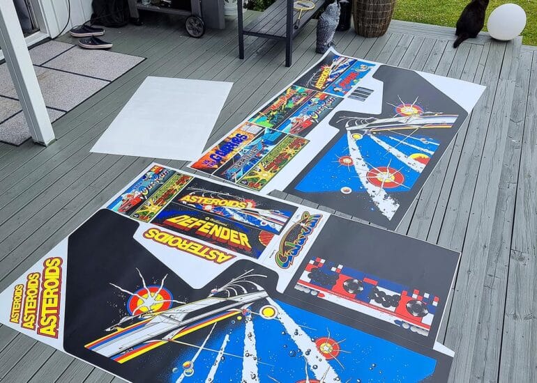
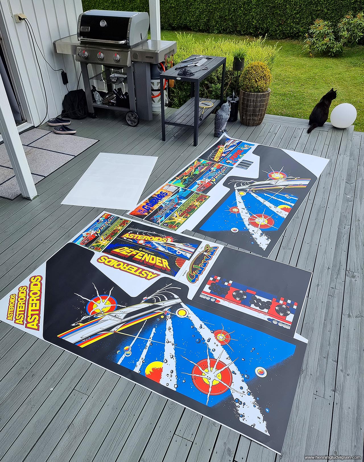
Vinyl decals
I also found some really nice looking Asteroids decals online that I edited to fit my template. I also added a bunch of marquees from other games in the available spaces since I’m paying per meter for the vinyl prints. I’m using a local business for my vinyl prints and the end result is amazing!
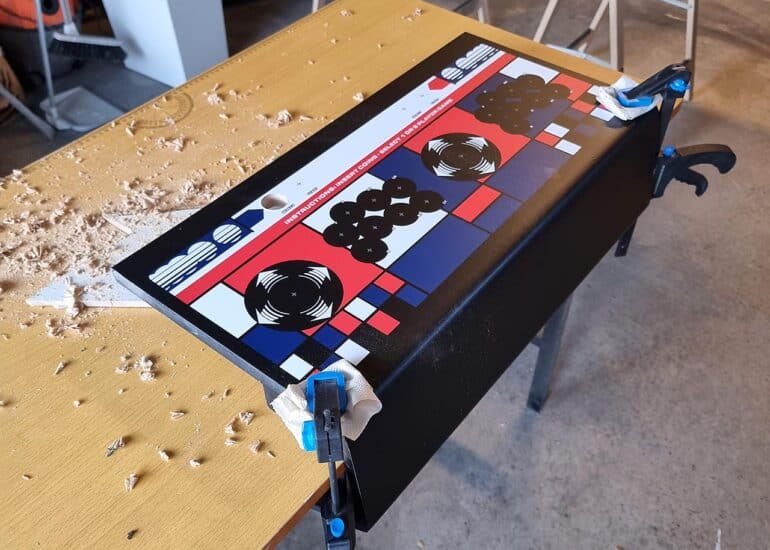
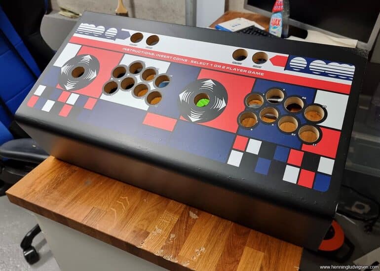
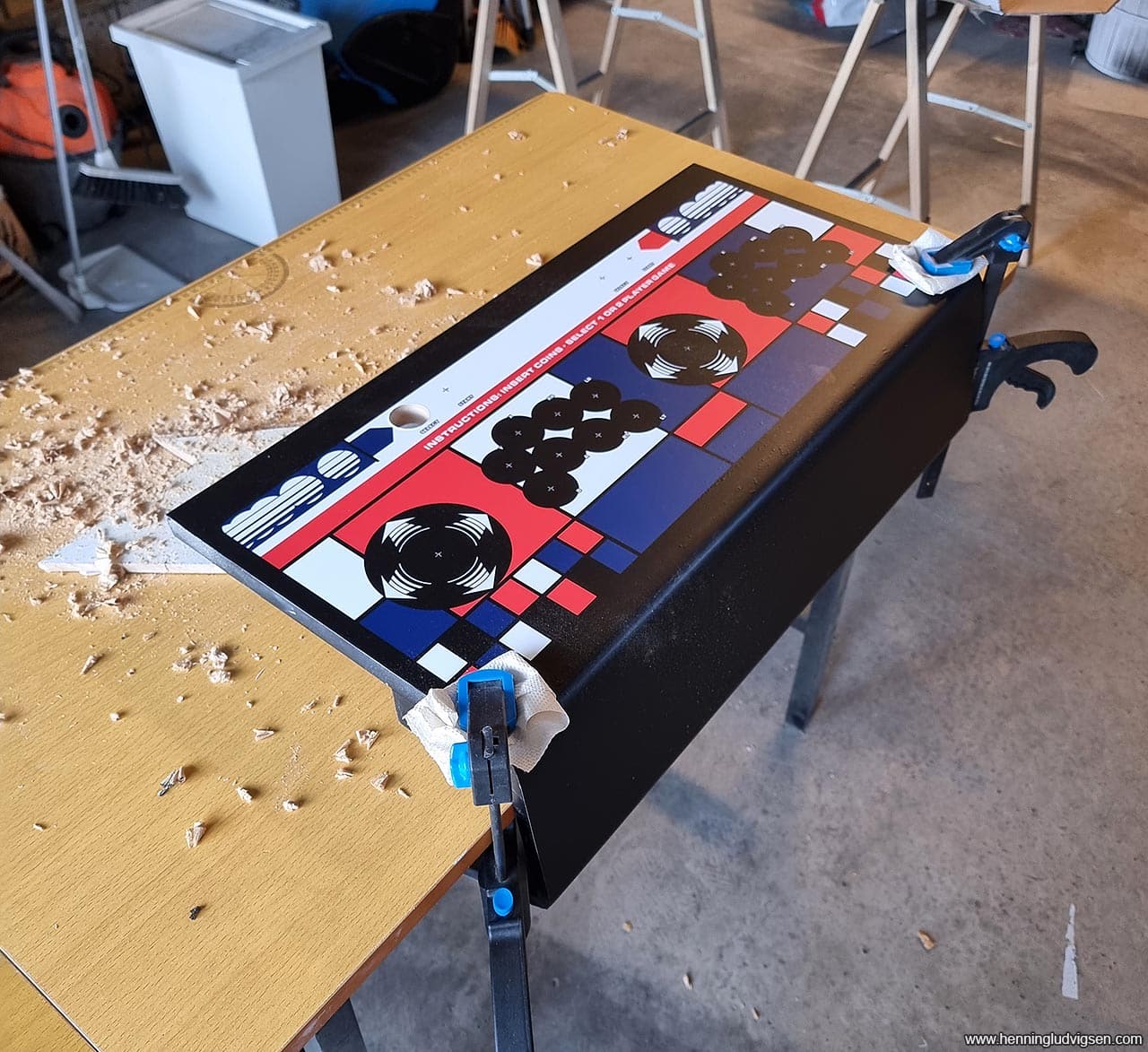
I mounted the vinyls on the control panel, and since the vinyl print has the template for the joysticks and buttons integrated including crosshairs for the drill, I used these as the guilde and cut all of the holes .
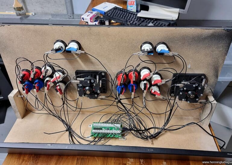
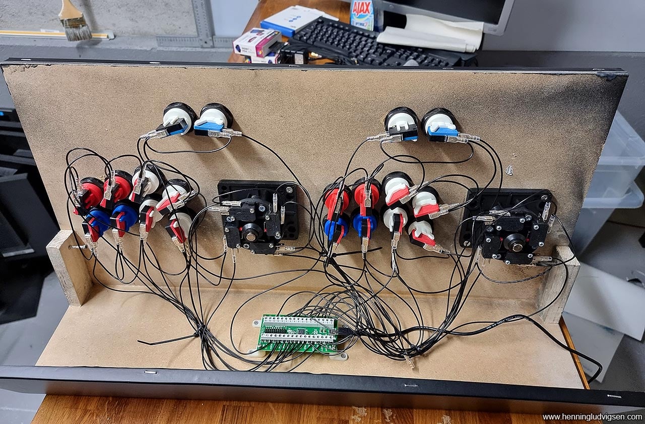
Connecting the controllers
I very much enjoy connecting all of the microswitches to the control board. It’s quite a bit of work but it feels great once you’re done and everything works. I’m using an IPAC2 controller board for this build. It has several modes, so remember to change it into the correct mode for your use. In this case it has to function as 2 separate controllers. It’s set to function as a keyboard by default which makes mapping complicated.
This controller interface board has 5 modes. Mode 1 = keyboard and mode 2 = two separate USB controllers, which I wanted to use. To change modes using the "Multi Mode" feature, do the following:
Start1+P1SW1 > Mode 1
Start1+P1SW2 > Mode 2
Start1+P1SW3 > Mode 3
Start1+P1SW4 > Mode 4
Start1+P1SW5 > Mode 5
I got most of my parts from ArcadeWorldUK, and I highly recommend them for anything arcade related.
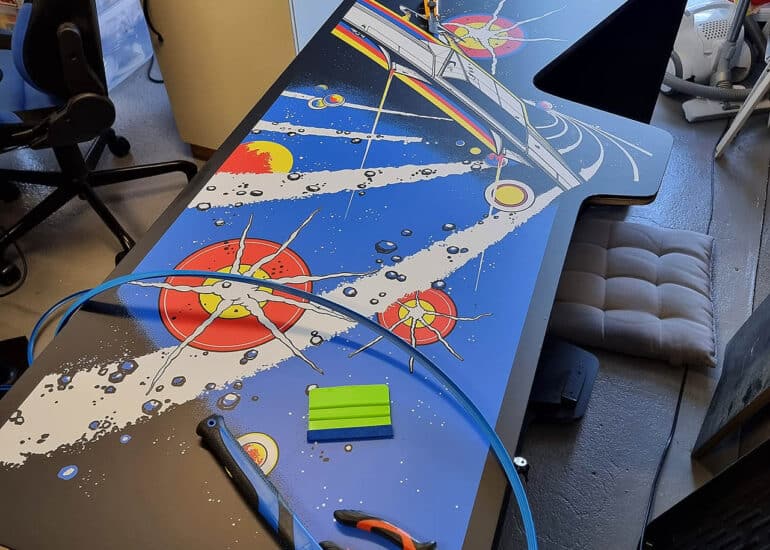
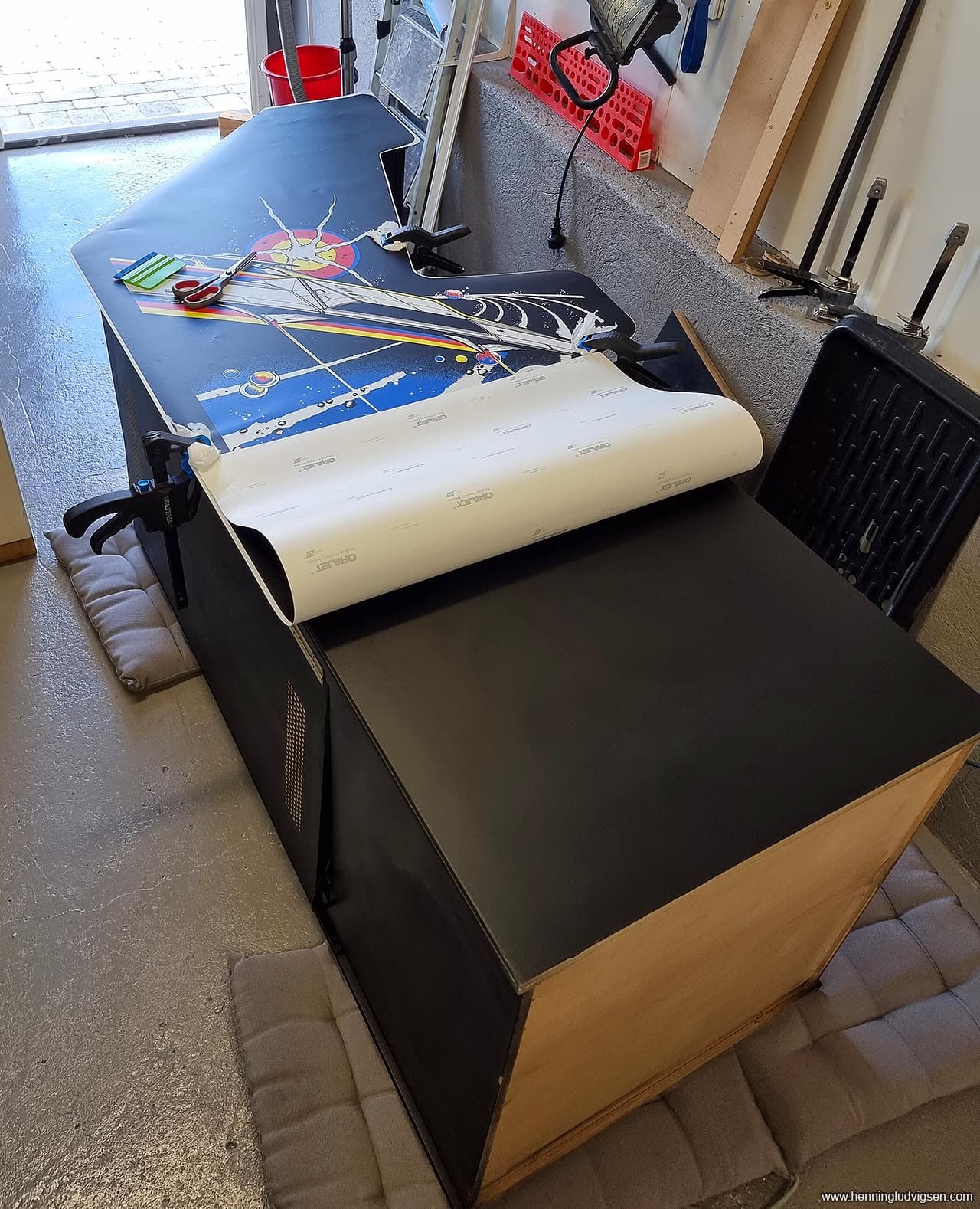
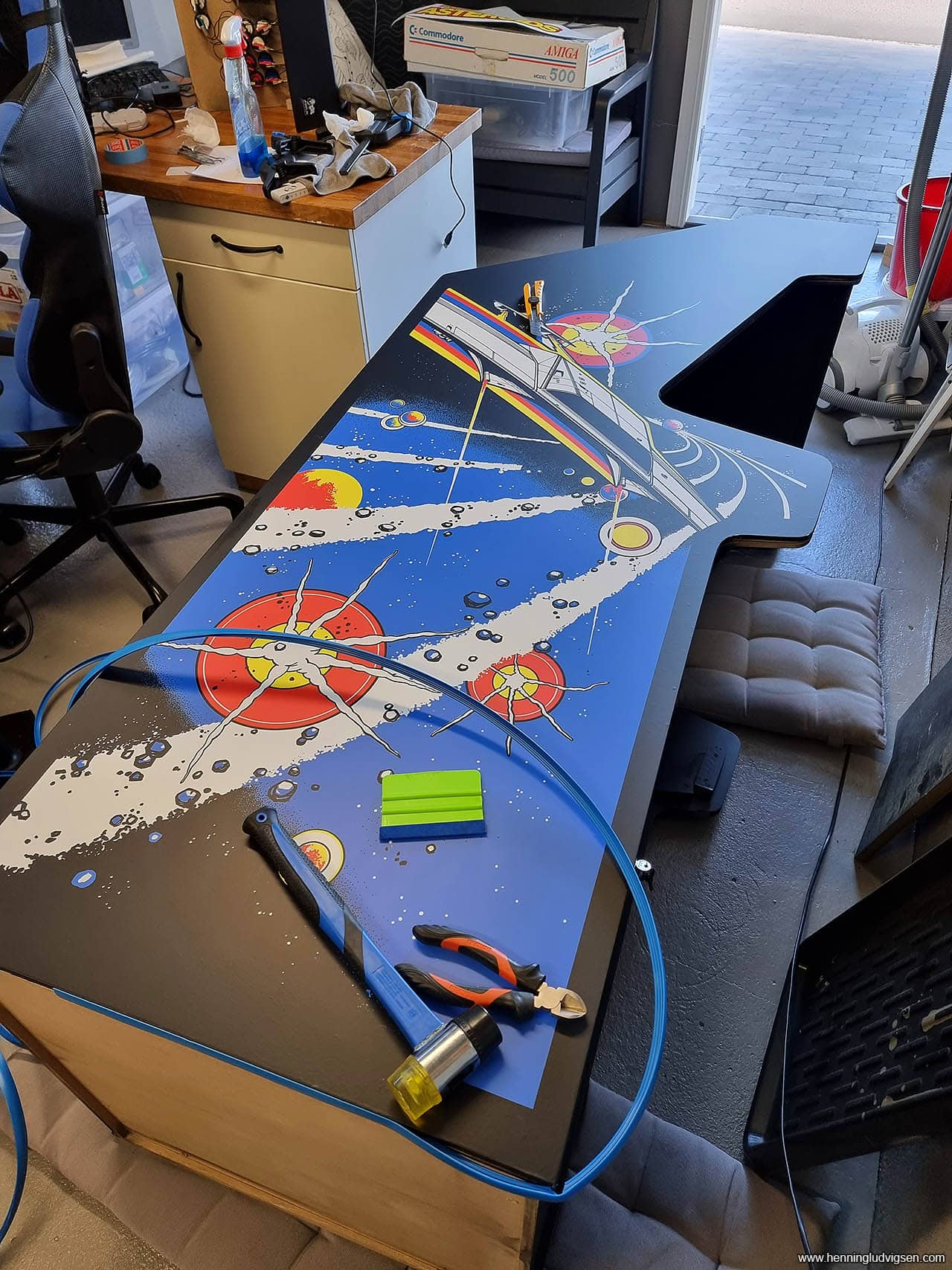
Applying the large vinyls
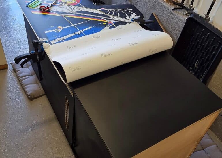
I started applying the vinyl prints to the side panels by tilting the cabinet over onto the floor and leaving the print loosely on top, to find the perfect placement for it. Then I used masking tape to «mount» it down on the top half. This way I can fold up the lower part, remove the protective paper for the sticker glue, cut it off, and then squeegeed it out from the center and towards the bottom of the cabinet. The taped down part will make sure you apply the remaining decal straight. Once the lower part of the cabinet is covered, I can remove the masking tape and carefully use the squeegee and push out all of the air bubbles all the way to the top. I got a few air bubbles on both of the control panel and side panels and was a bit disappointed with that until I realized that the bubbles would disappear within a few days, yay!!!!
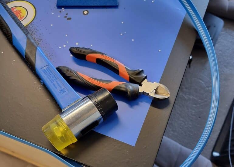
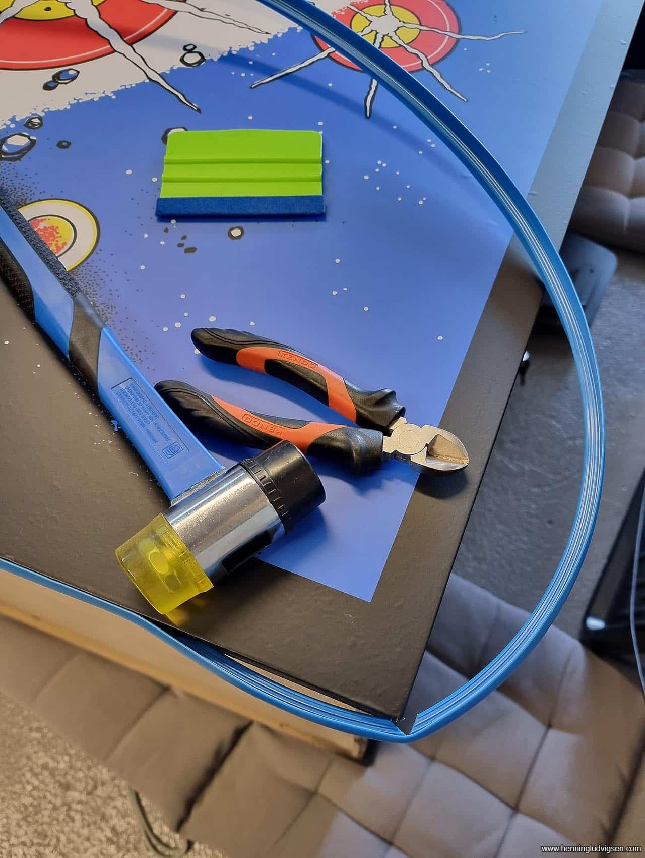
T-molding
The T-molding was applied from the bottom of the cabinet using a rubber mallet to carefully hammer it into the side slit. On the outer corner I had to cut off a wedge to male sure that the lip bends nicely around the corner. On inner corners only some cuts are enough to make sure it bends nicely the other way as well.
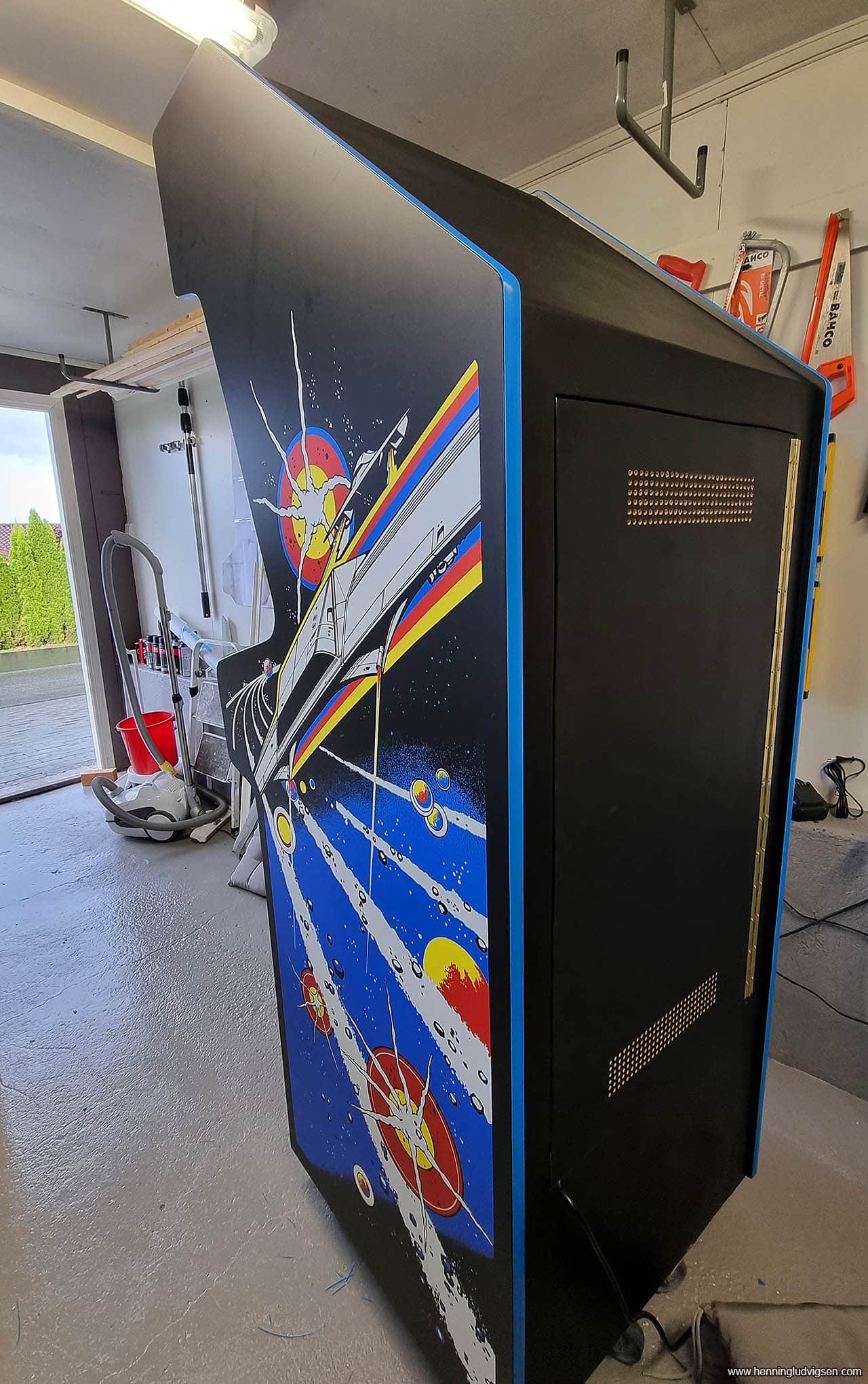
It's starting to look like something with decals and t-molding applied.
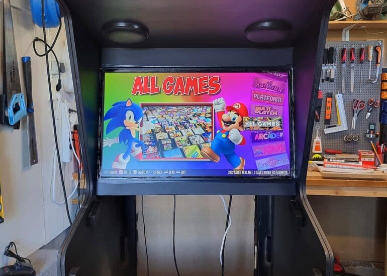
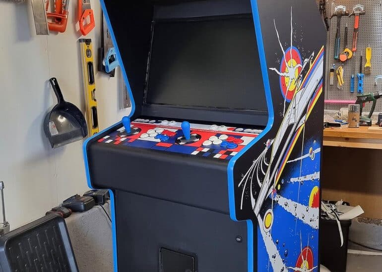
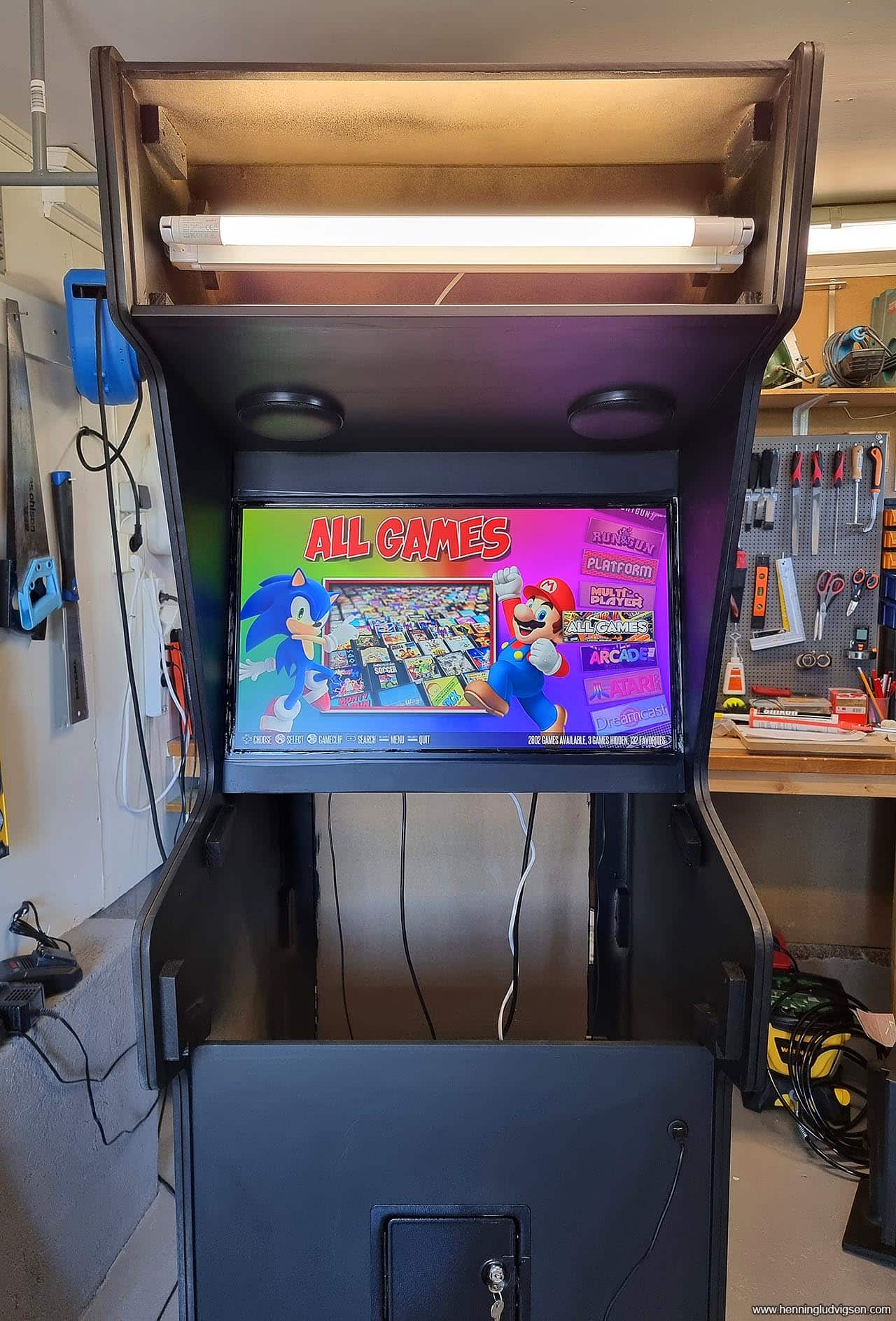
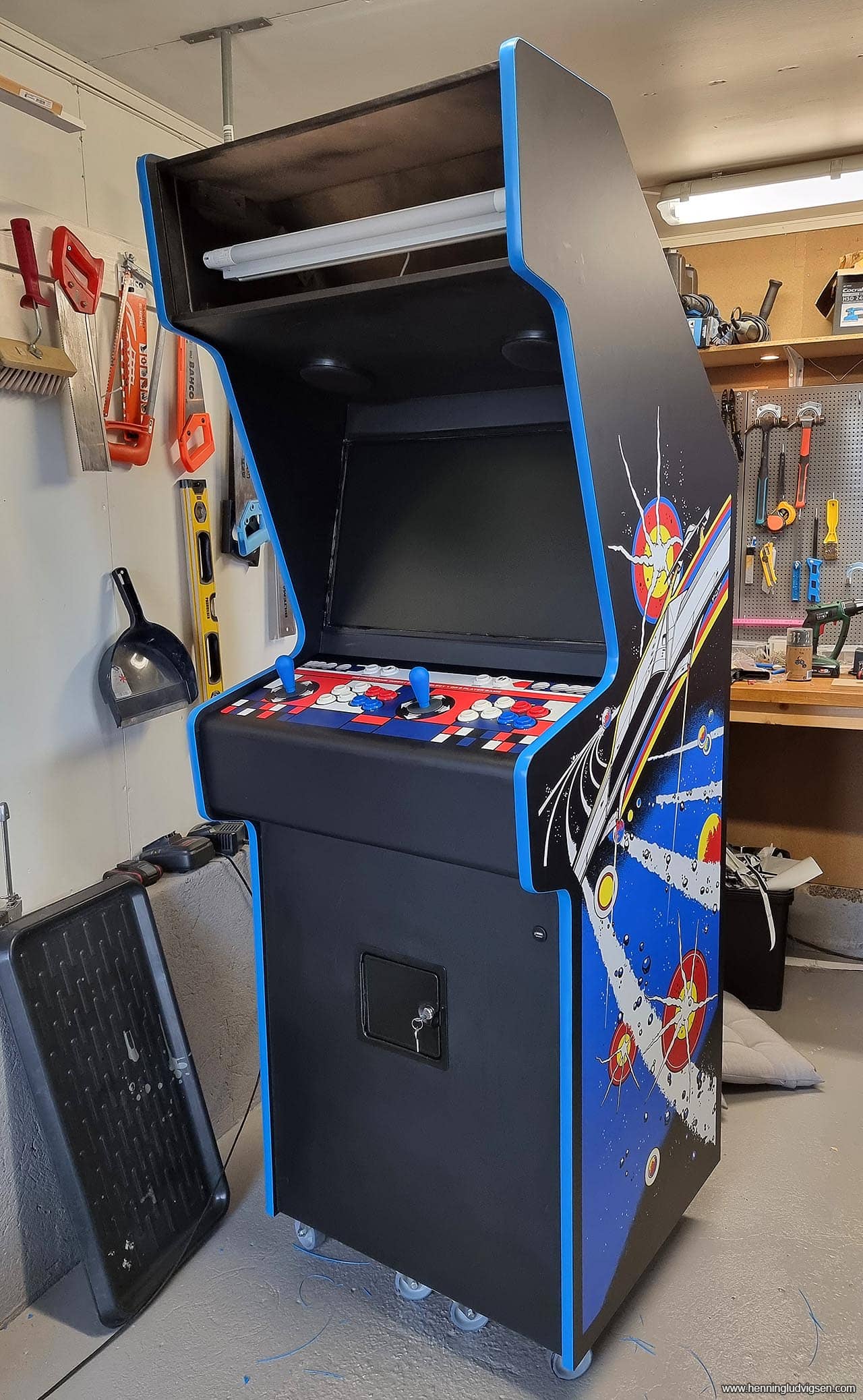
End results
End result with bezel and marquee art in place. The bezel print was printed on the backside of transparent vinyl to go on the backside of the plexi glass. I’m super happy with how it turned out. It plays great, the controllers feel nice and tight, and the full width of the 27” screen makes for a great game experience! And… It’s heavy… It’s VERY heavy!
I LOVE the cabinet design, and your plans will be very useful for me. I see, however, that you opted for the “fighter stick” button layout. Asteroids is certainly playable with this layout, but I’ll be going for a more Asteroids-specific layout, except I’ll be using two center buttons instead of just one. With a left joystick, it will also be very compatible with both Defender and Stargate, as well as lots of other Golden Age classics. I was in junior high and high school (class of 84) during that era, and didn’t get into the later fighter games, like Street Fighter, Mortal Kombat, etc, so the fighter configuration doesn’t make much sense for me. But the cab ideas are TERRIFIC and I appreciate the information!
Thanks for your comment! Yeah, I would have loved to have the space to make this a more authentic dedicated Asteroids only cabinet, but I wanted to maximise its use and be able to have a few thousand games available, hence the control panel lay-out. It’s easy to make an alternative control panel that can be swapped out as well 🙂
Awesome build! I’m very impressed! I’m picking up an empty Asteroids cabinet tomorrow and I’m not nearly as good as you with Photoshop. Is there any way that you could share your control panel file? I have plans on doing the same thing with a fightstick setup and I think that yours is perfect! Thanks in advance either way and also for sharing your process, it was very interesting and inspiring.
–Stu
Thanks, Stu! Getting a real Asteroids cabinet sounds really great, congratulations on that! I’ll send you a download link for my edited control panel though the email you posted. Just let me know if you didn’t receive it 🙂
Thank you so much! I really appreciate it!
Hi Henning! It’s Stu again. I was wondering what model of TV did you use? I like how it turned out and was thinking about doing the same thing. I bought a used 19″ monitor but I want to go bigger and it would involve too many mods and the price of large crt’s is out of control right now. My next question is if you could share the file for the bezel graphics also? It came out so good and I’m thinking that that is the way to go. Thanks in advance, you’ve been a big help!
I’m not sure if my last message got through but I was wondering if it was possible to get the file for the monitor bezel also? I’ve been trying to figure out something that will fit width-wise and I’m not having any luck. You said that you got a 27″ to fit? My cabinet is 23.5 inches wide at the opening and all of the 27 inch models land somewhere in the 24.5 inch range. Any help with a model would be greatly appreciated! I love what you did by incorporating the side art into the bezel and would love to do that too as yours turned out so well. I’m not planning on ever posting it online anywhere ever so I won’t be stealing your thunder as I know a lot of hard work went into your build and I wouldn’t want to take that away from you. Thank you for all of your help! —Stu
Hi Stu! I missed your previous message, sorry about that! I used a fairly standard, older Philips 27″ monitor that I got from a friend. Nothing special, but it works quite well. Sure, I can share the bezel with you. No problem at all! Do whatever you want with it 🙂 I’ll send you a link on your email ASAP!
-Henning