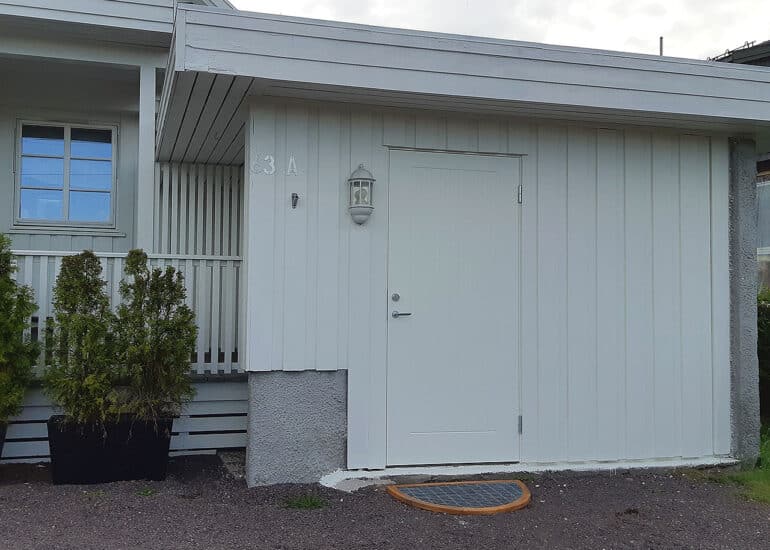
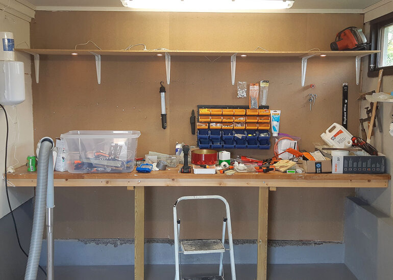
Getting set up and started
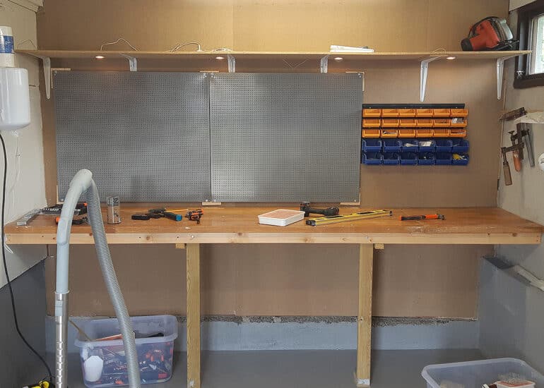
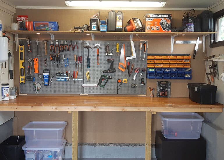
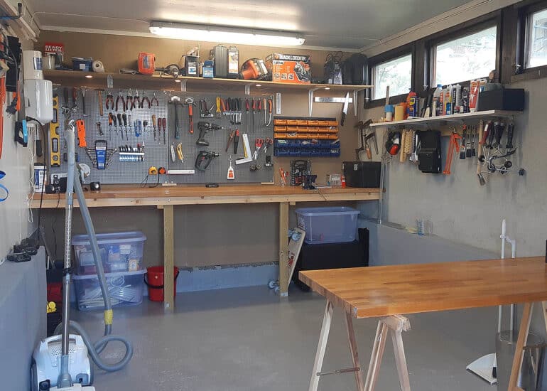
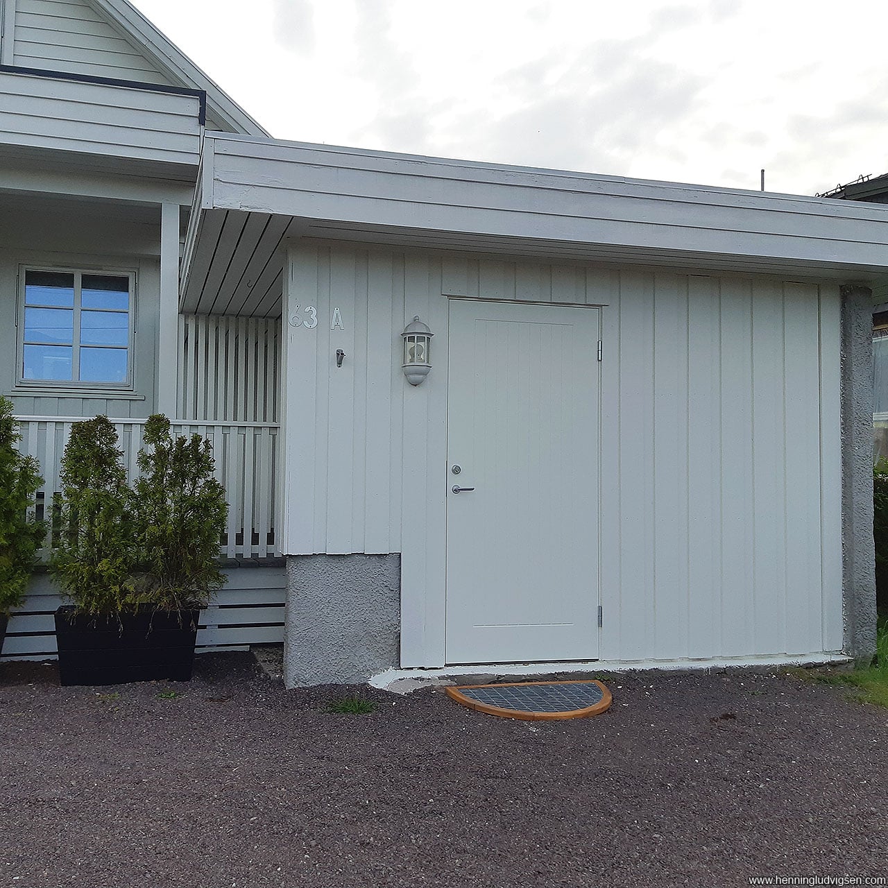
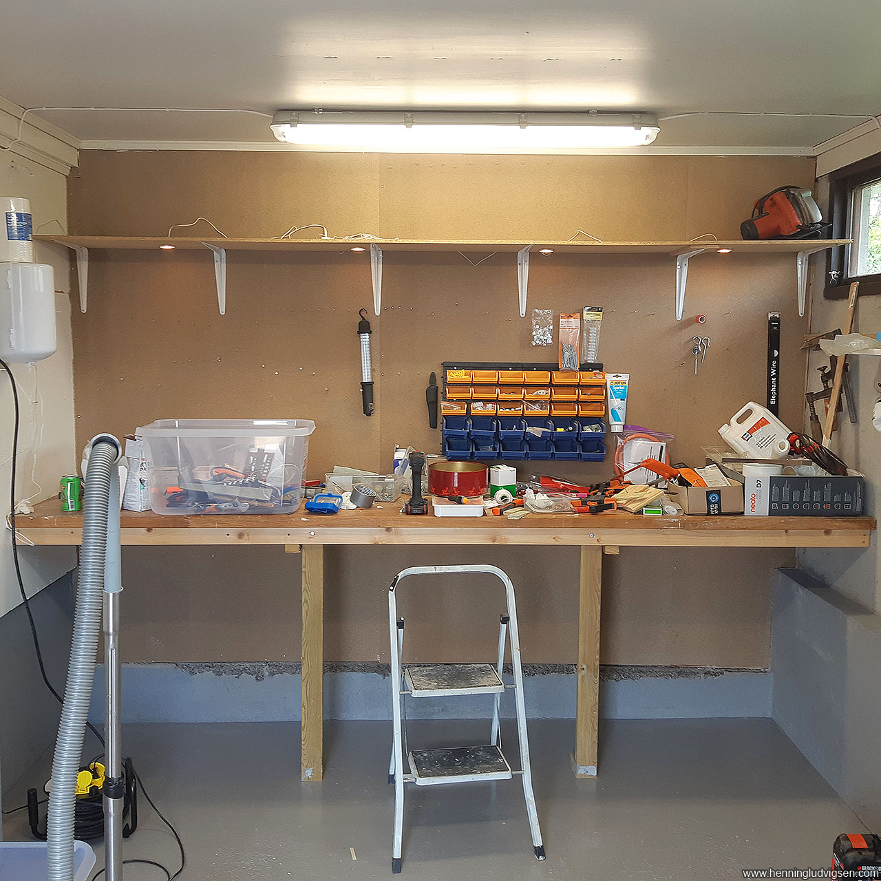
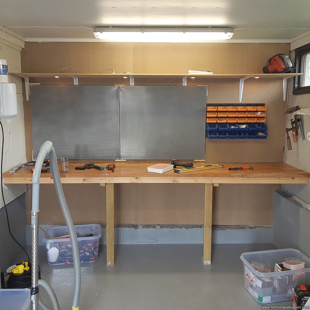
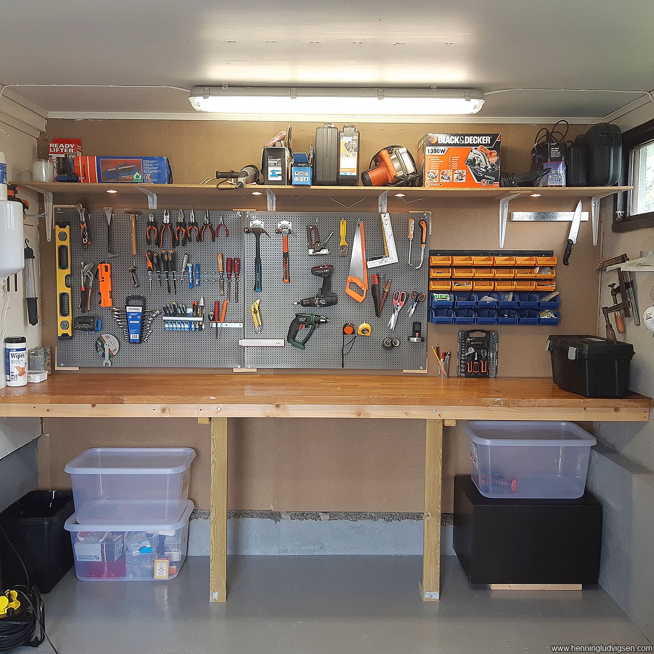
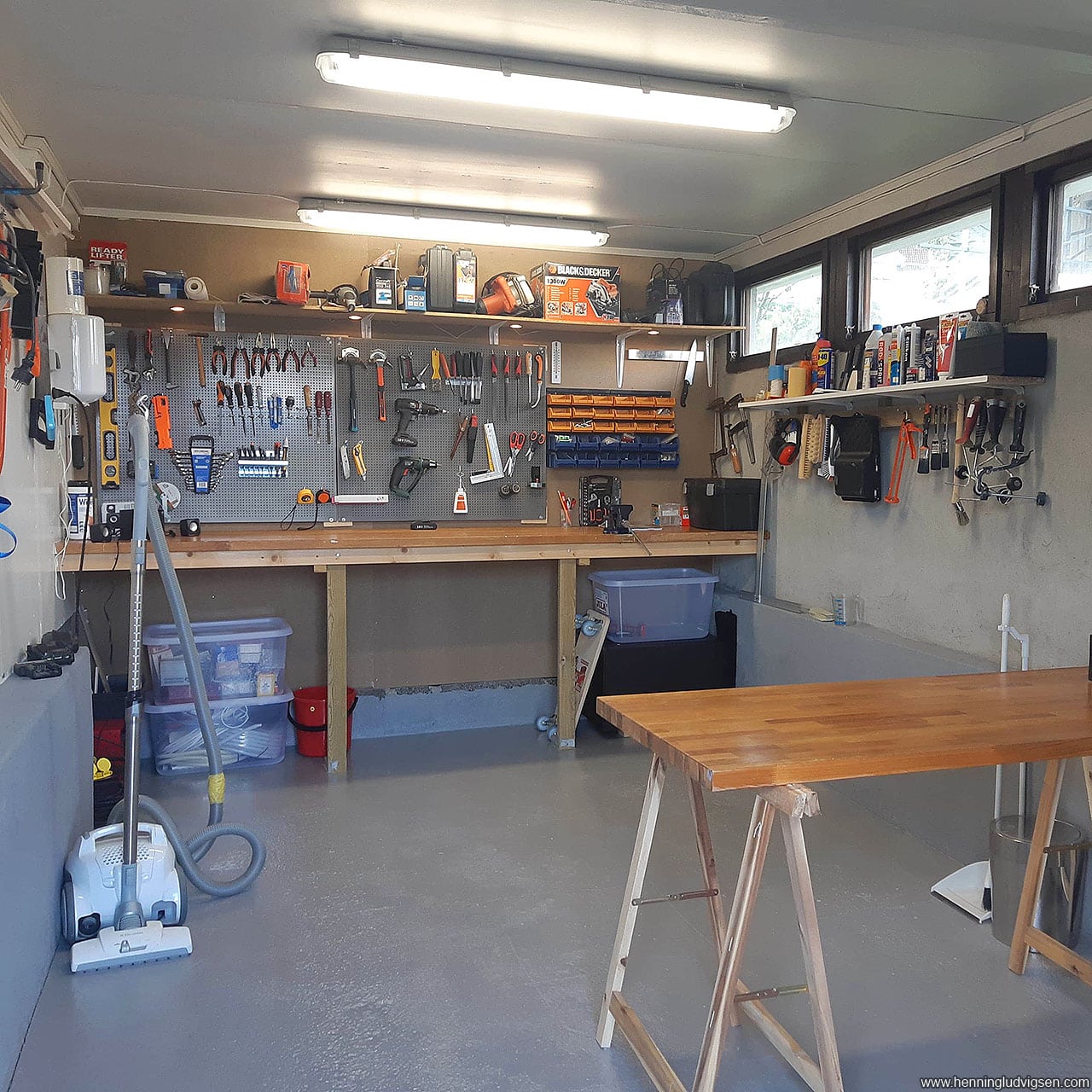
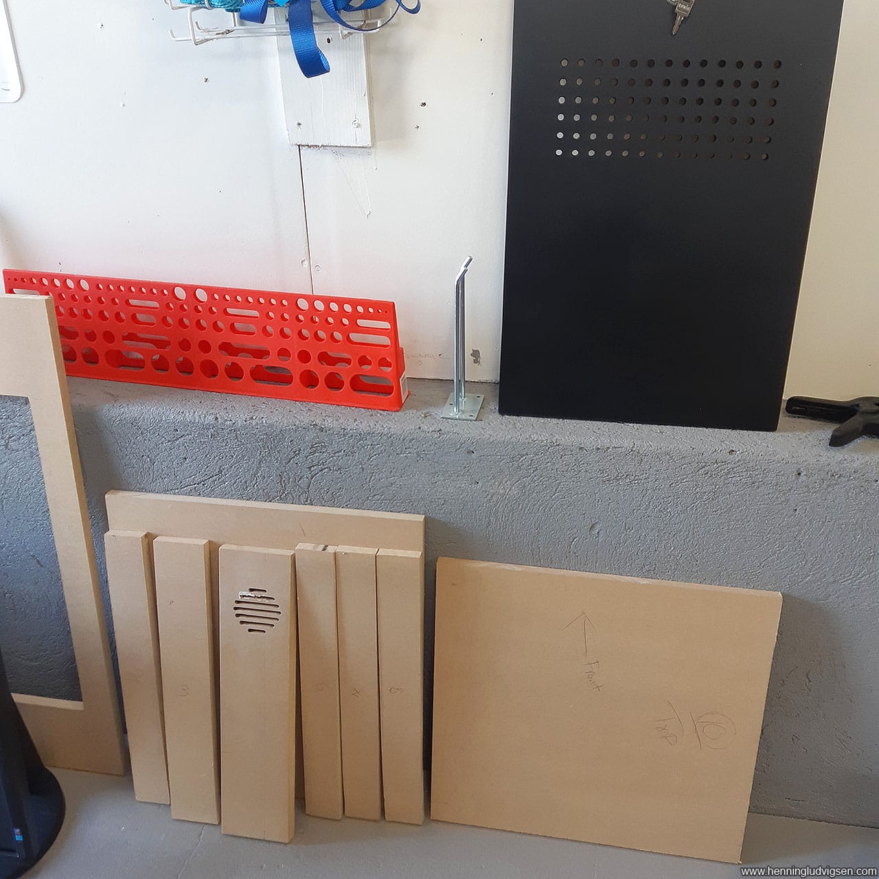
I’ve got 2 garages, and I kept one of them as a messy tool shed ever since we bought the house a few years back. I decided to remove the old garage door and add an isolated wall and door, and treat the floor with epoxy. Next I ordered some tool organizing systems and bought tons of tools and materials.
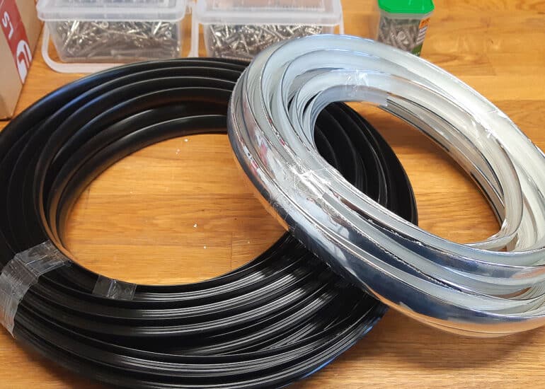
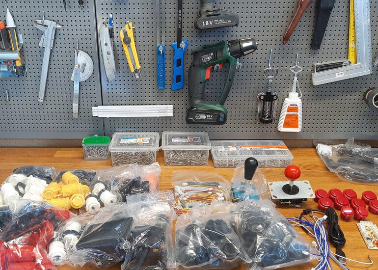
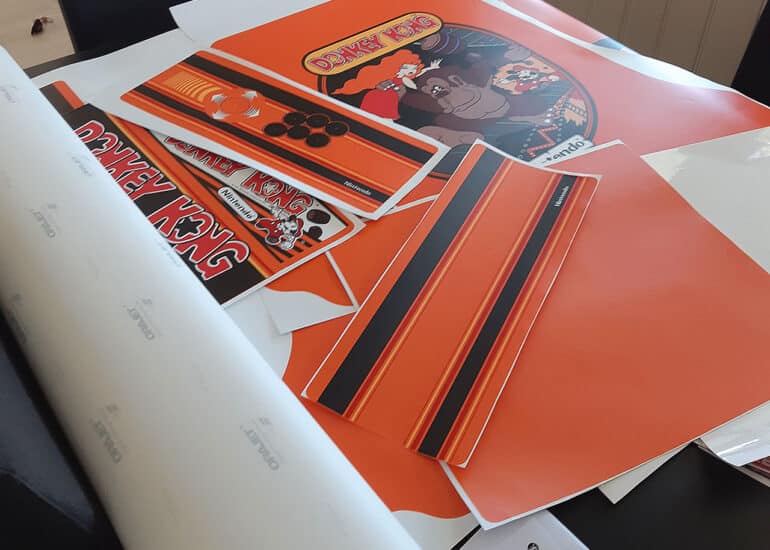
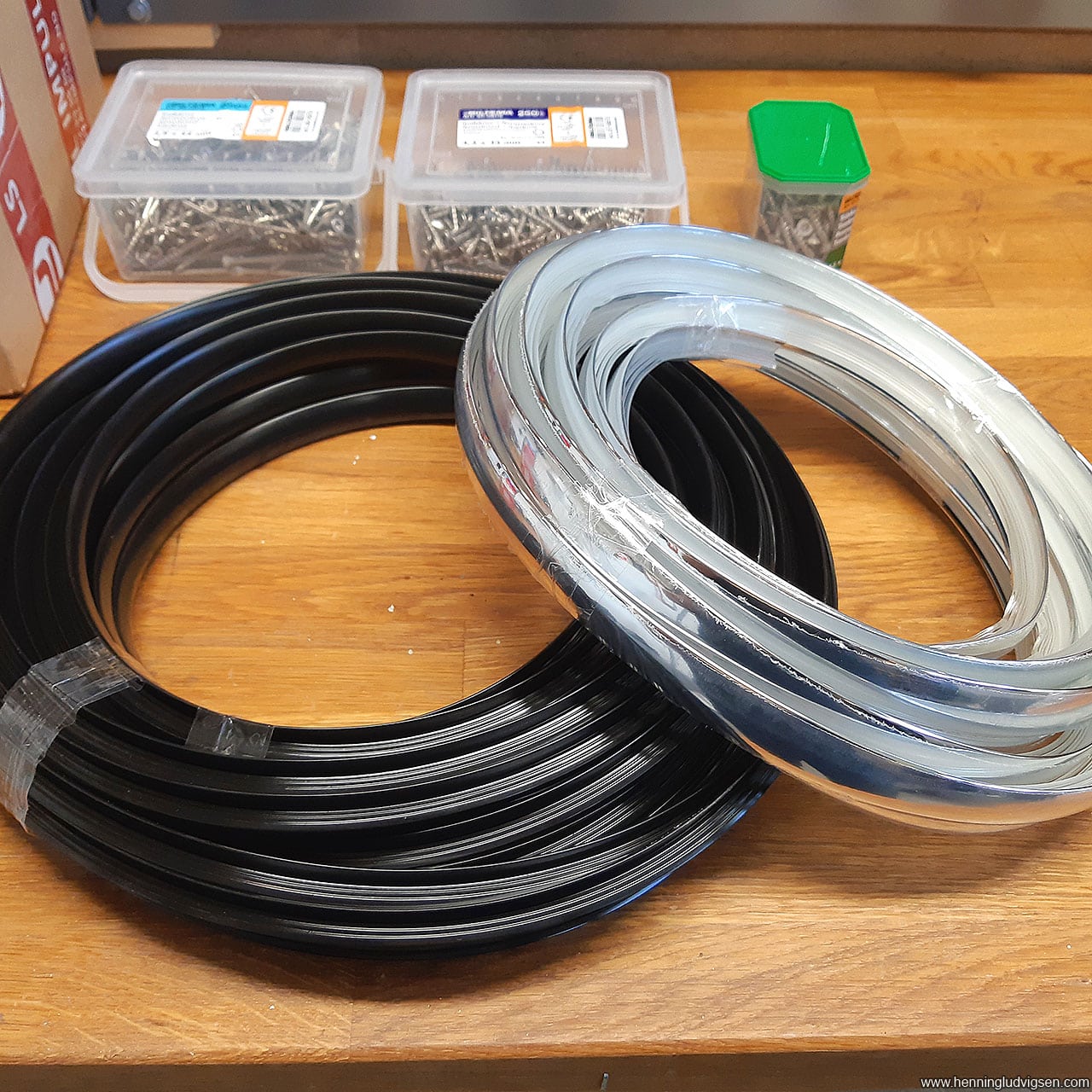
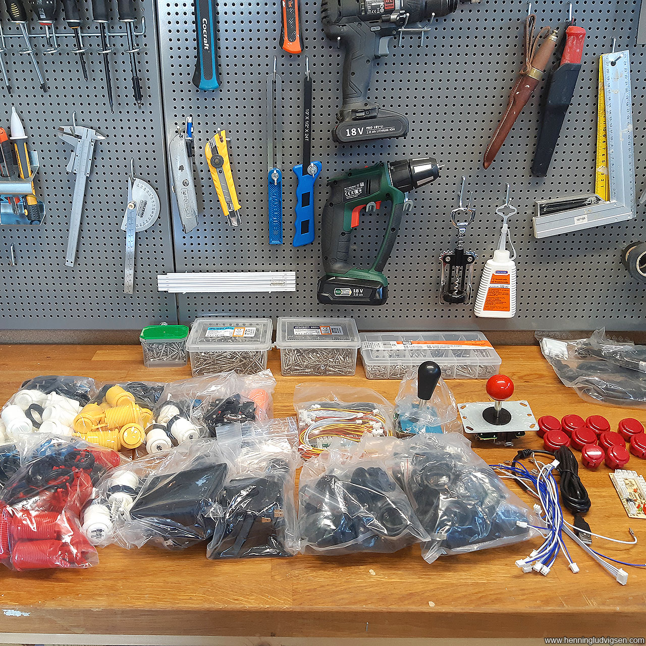
As I’m located in Norway, there’s basically no options for purchasing any proper arcade related parts, like buttons, joysticks, etc, so I started ordering from abroad which is super expensive over here due to shipping cost and additional toll and tax cost. Oh well… I made sure to order enough parts for a few future projects as well.
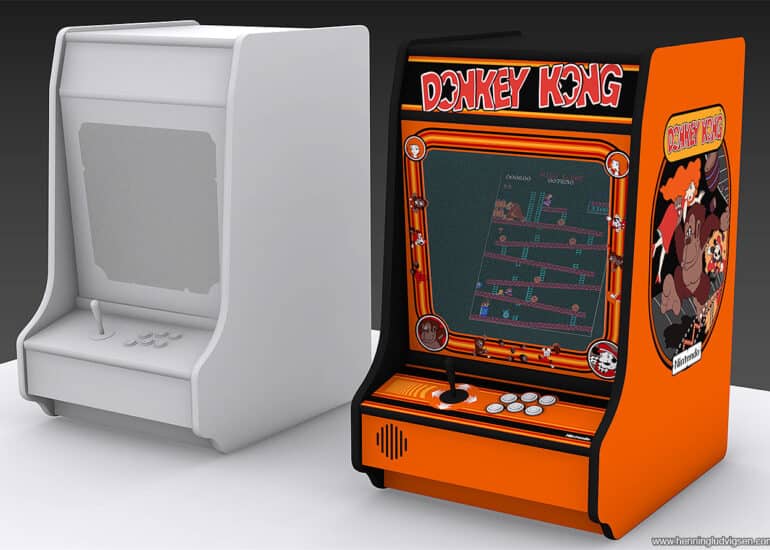
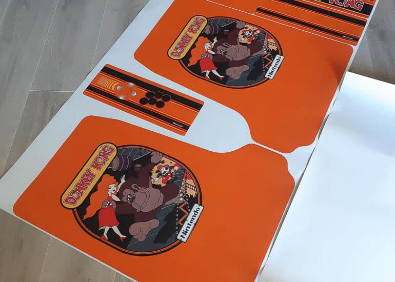
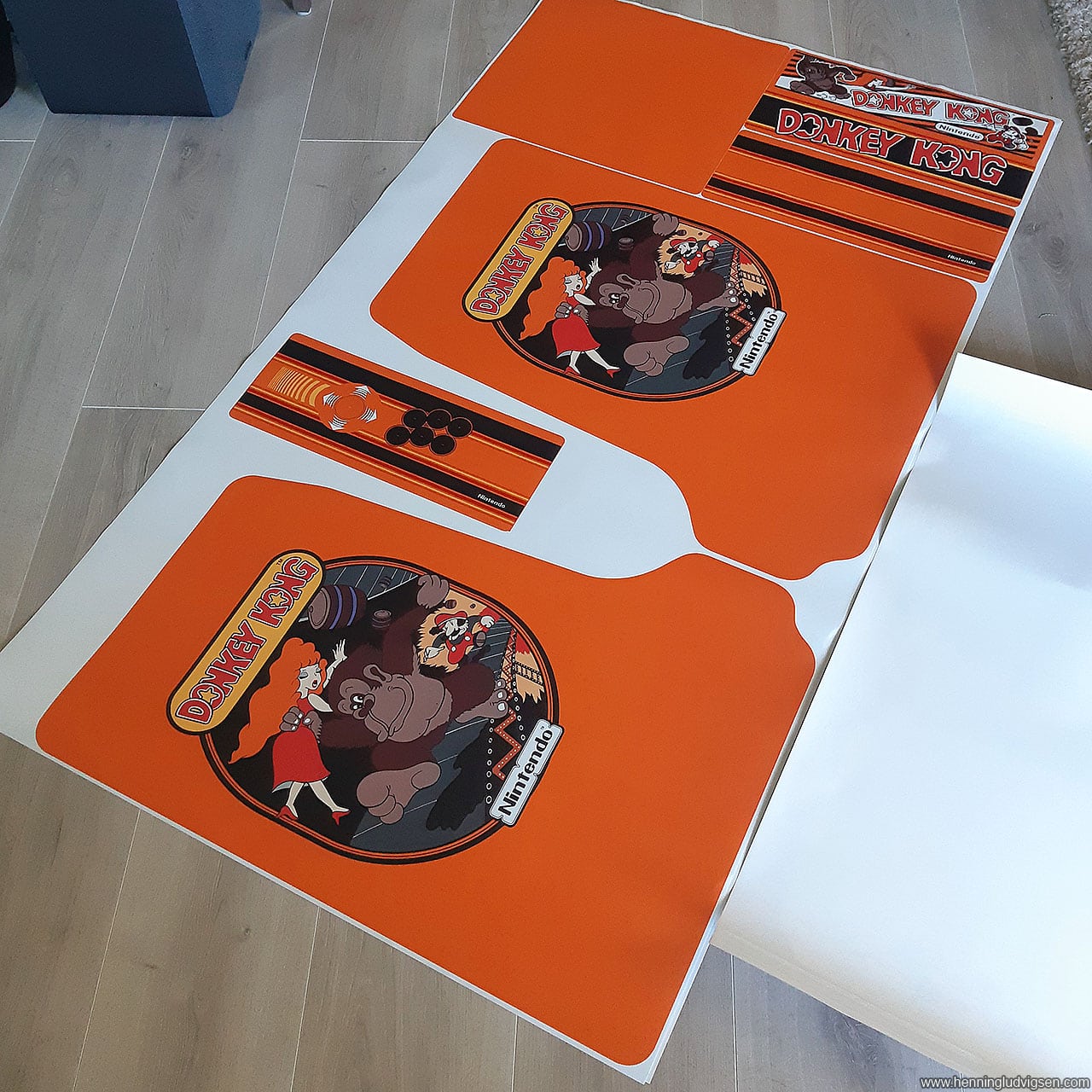
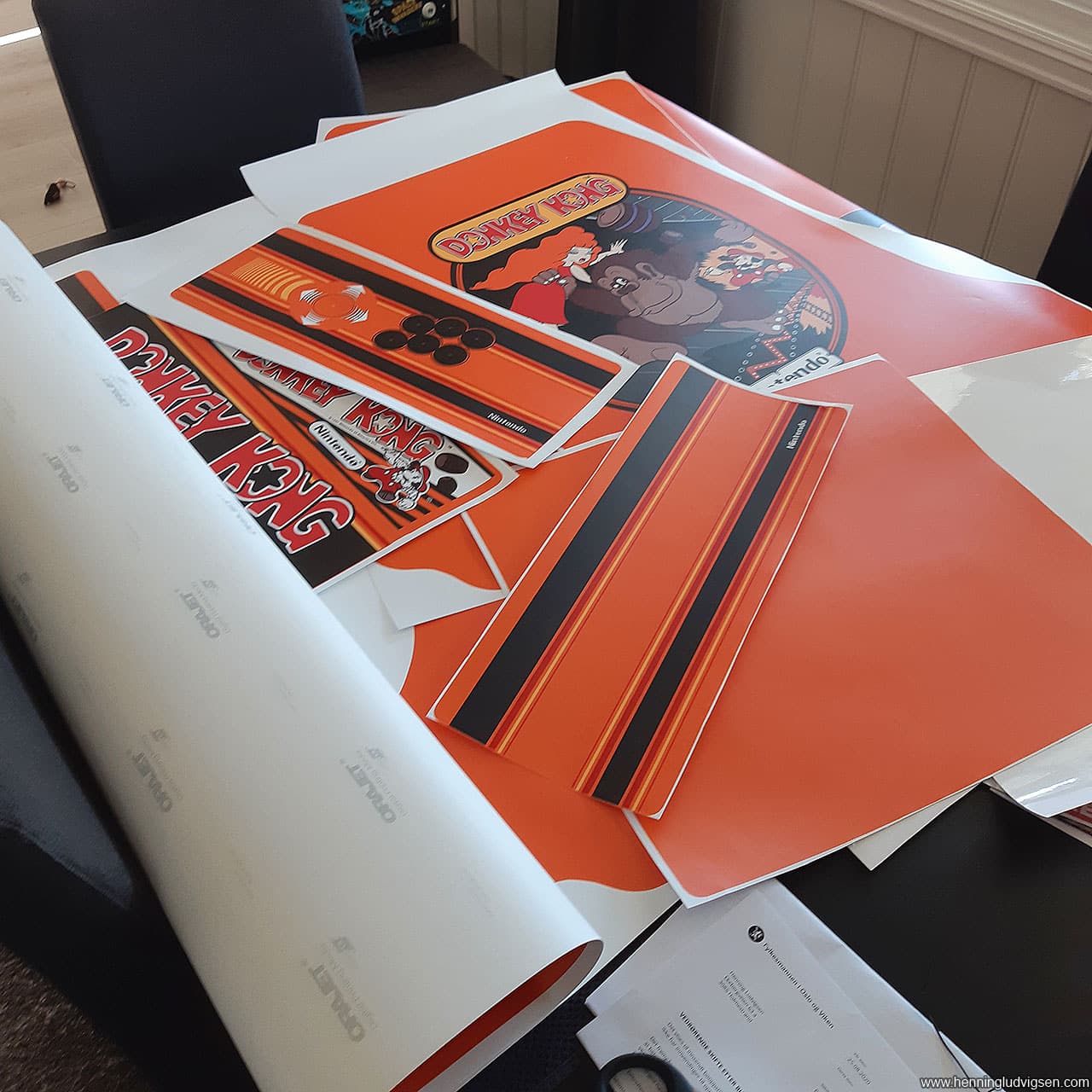
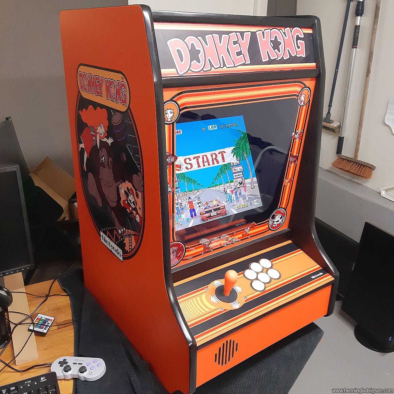
I started by creating the arcade cabinet in 3D Studio Max, to get the measures I wanted and see what it would look like. I also found high resolution artwork of the classic Donkey Kong arcade cabinet that I tweaked into a brand new colour scheme and made a few different and new elements. I wanted something that look unique but still honored the good old classic game.
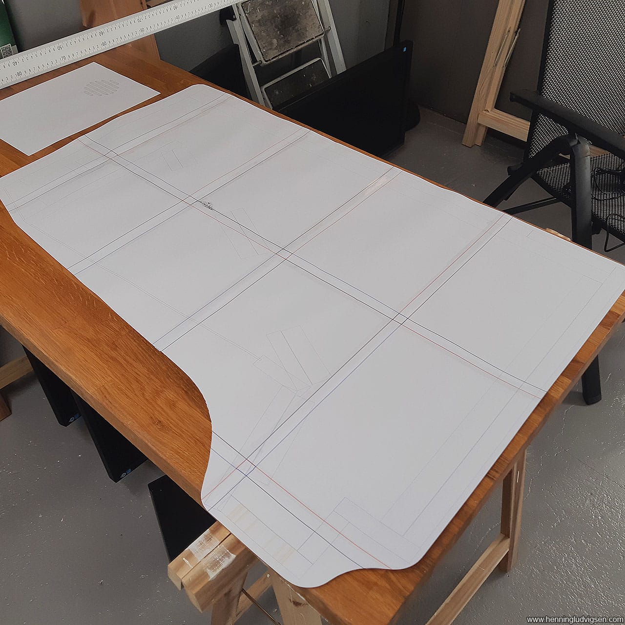
Next, I rendered the side wall of the 3D model including the placement of the horizontal elements into a line art image at 100% size.
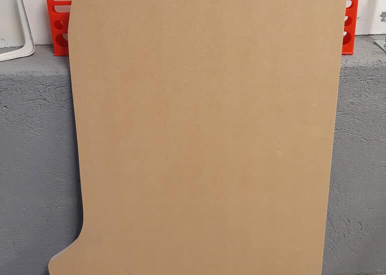
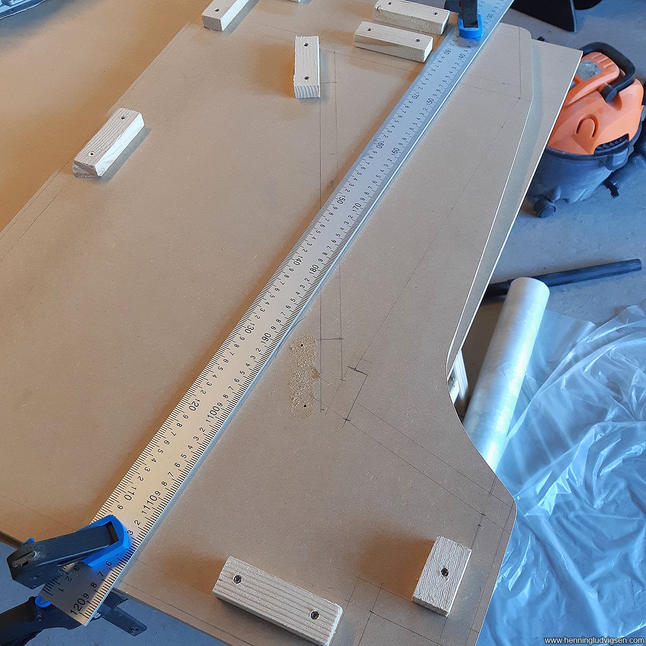
Next, I printed it out and taped together the pieces into a physical 1:1 sized template.
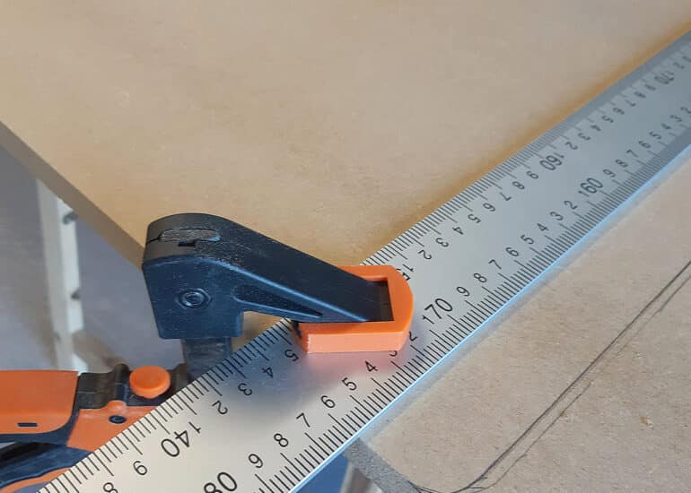
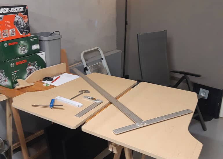
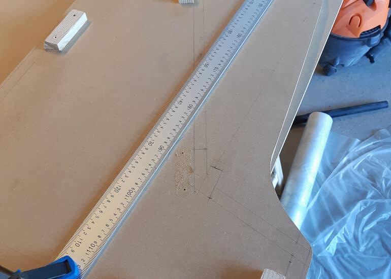
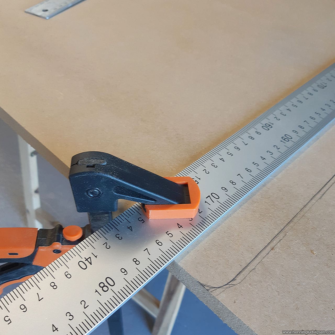
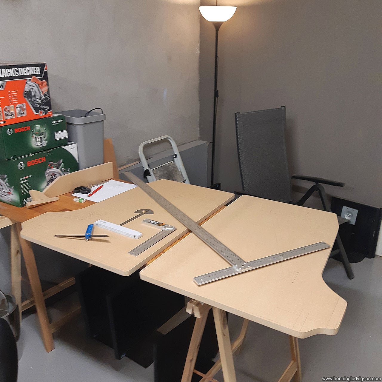
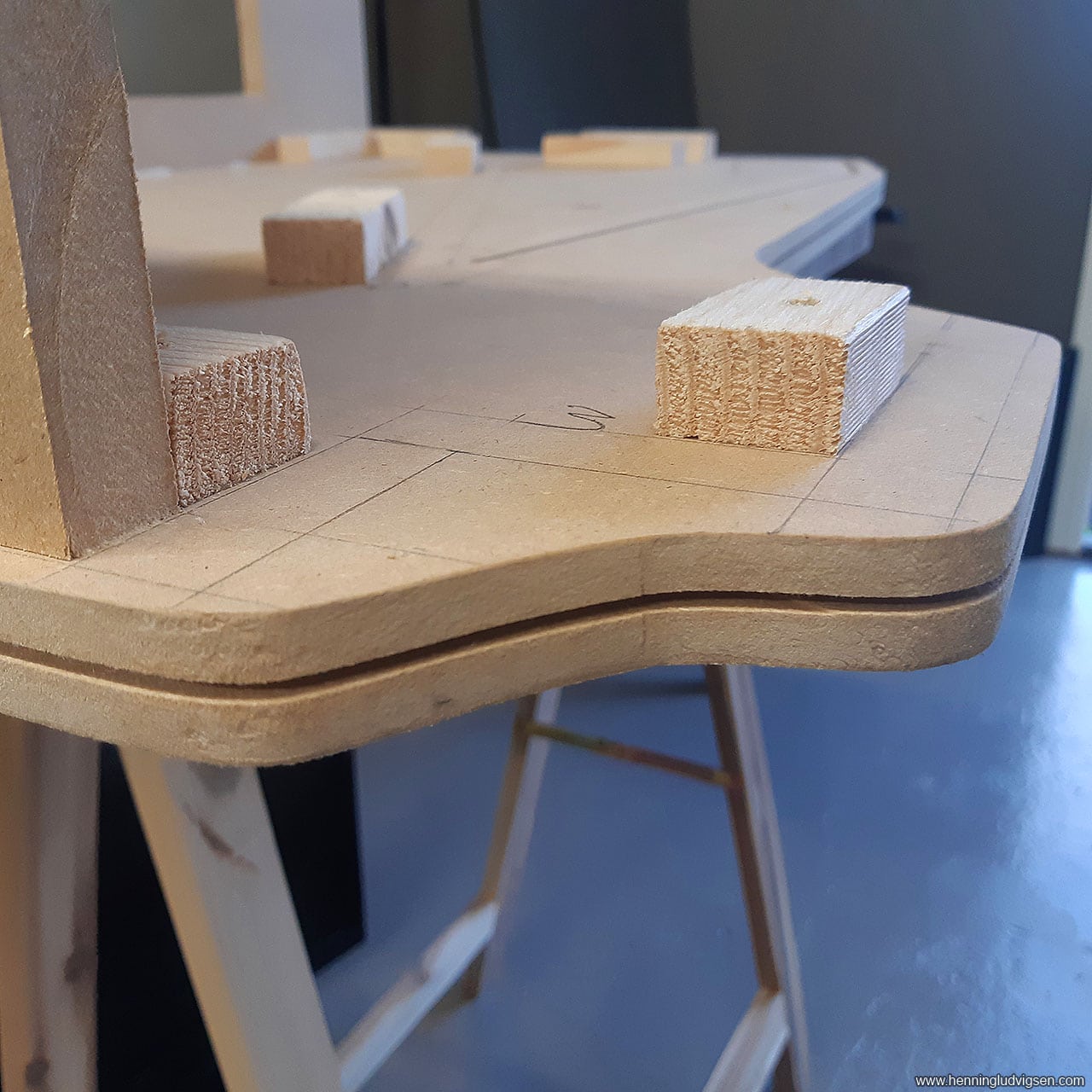
I used this template to draw up the cutting lines onto the MDF and cut it out with a circular saw with a ruler guide on the straight edges, and a jigsaw on the curved areas.
I put the paper template on the wall so that I could easily measure the connecting pieces later.
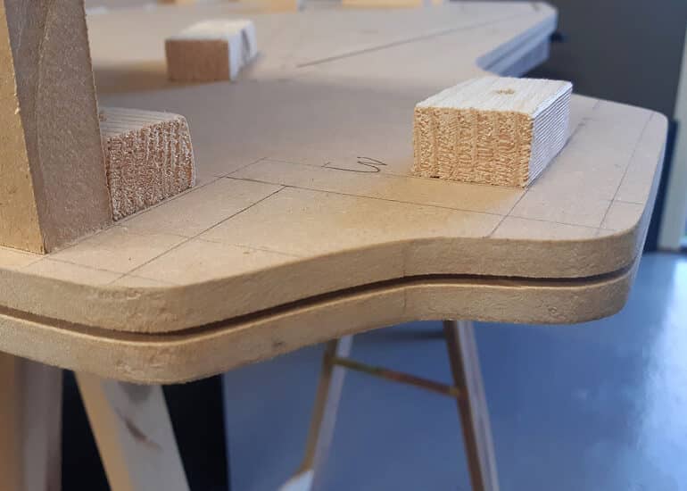
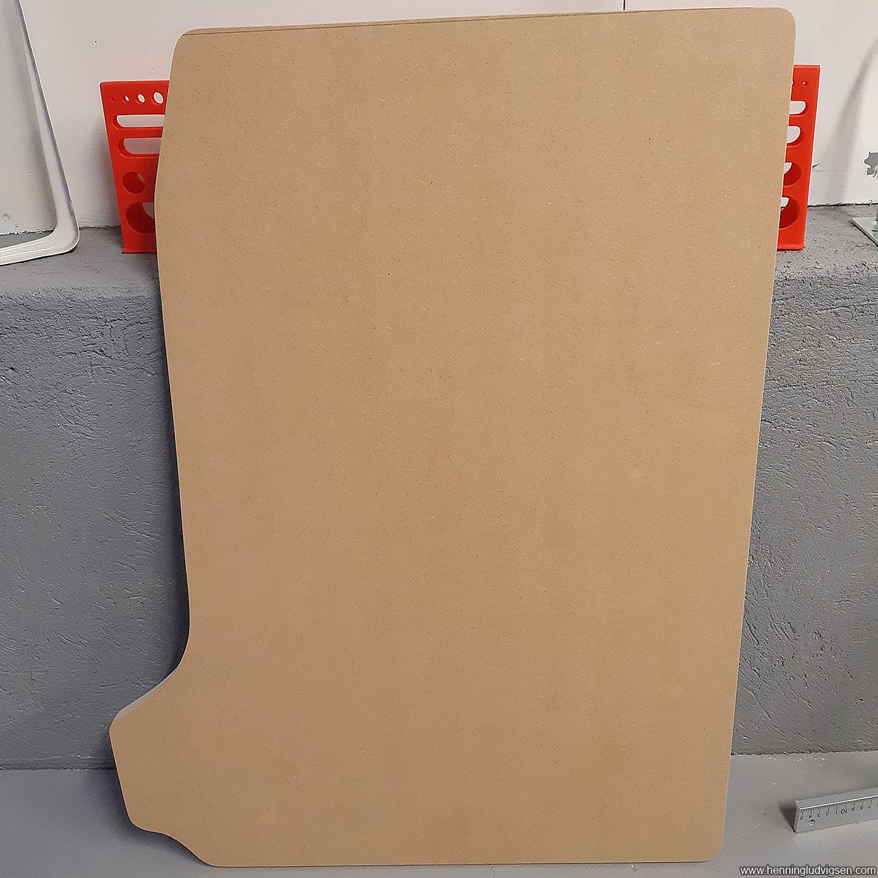
Next, I wanted to cut the second side wall and used the first side piece as a template and traced it onto a piece of MDF. I quickly realized that no matter how freaking careful I was when cutting the other side, it was impossible to get it identical. To fix this, I clamped both pieces together and used a sanding machine with a rough grit paper until both pieces matched up perfectly.
According to the internet, a good way to get a proper copy is to clamp the original MDF onto a slightly larger copy and trace it with the router and a fitting drill bit for this purpose. Perhaps next time!

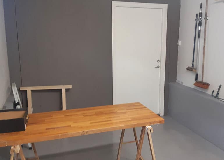
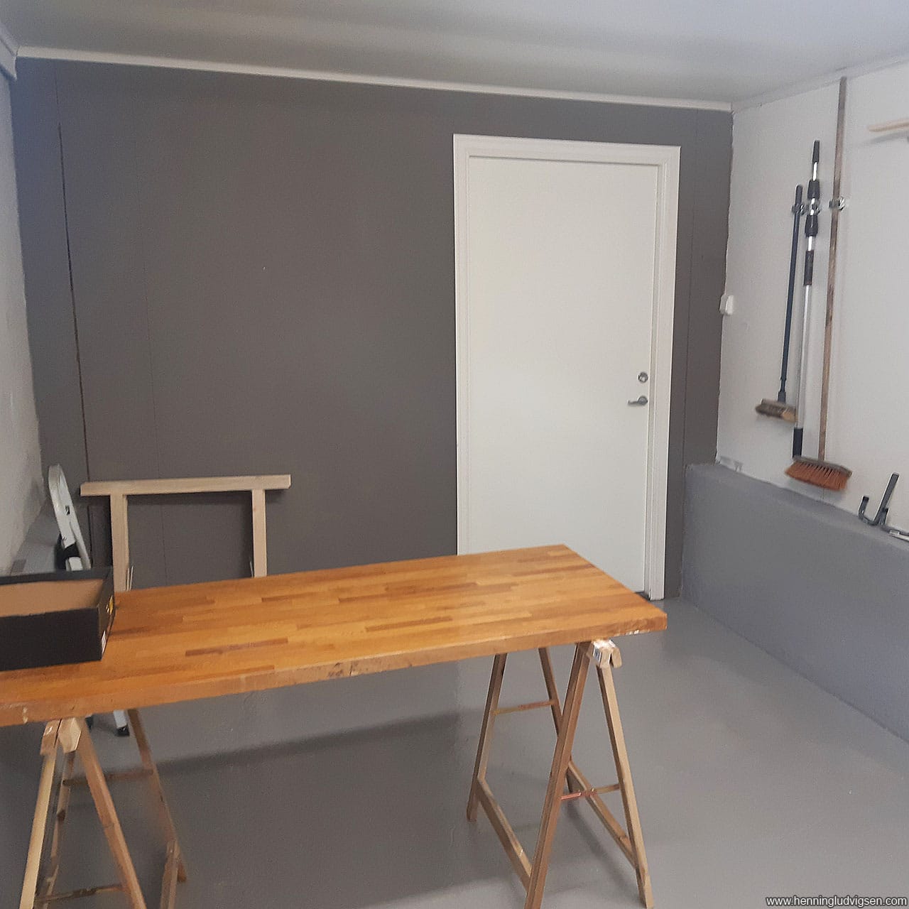
And DAMN, the MDF is generating A LOT of dust, so make sure to use a mask when cutting and sanding. I used my 2nd garage for cutting and sanding to avoid having my workshop completely covered in dust.
Stripping the screen
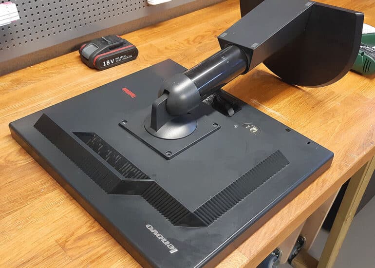
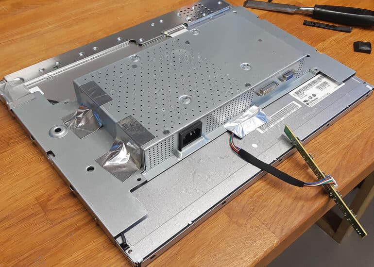
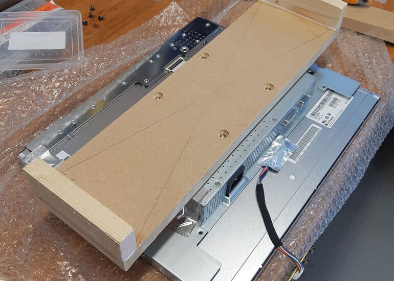
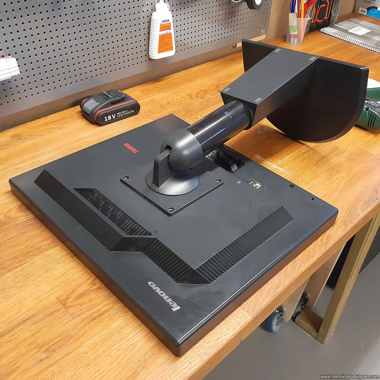
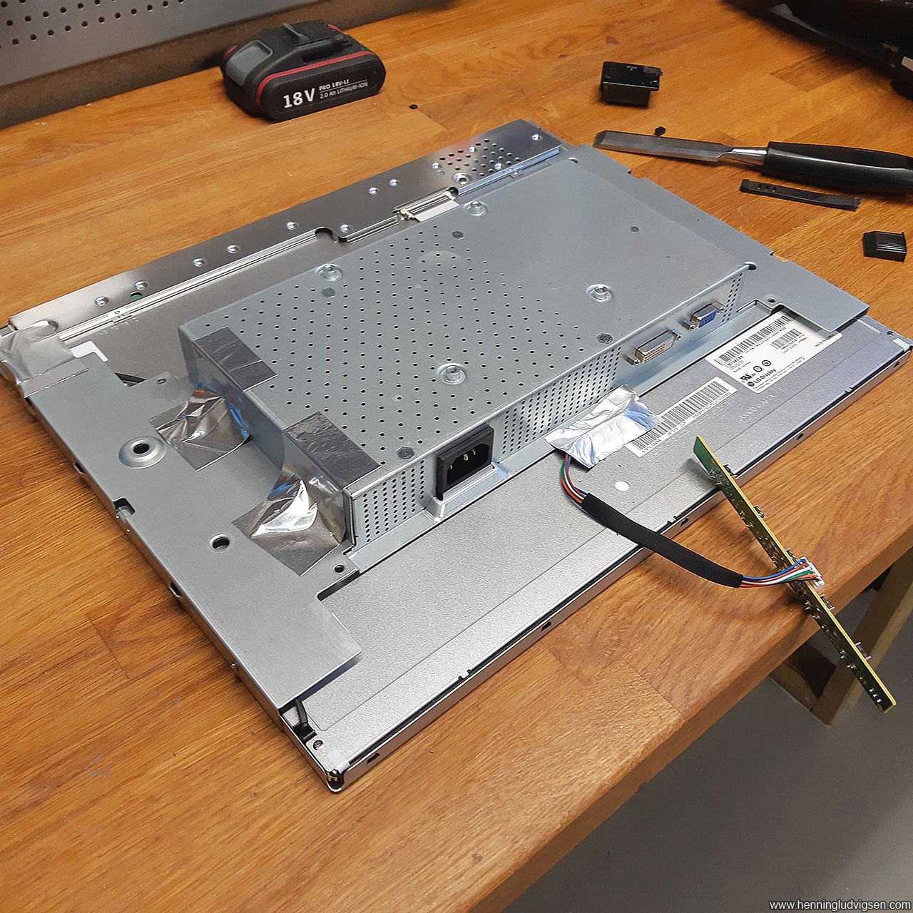
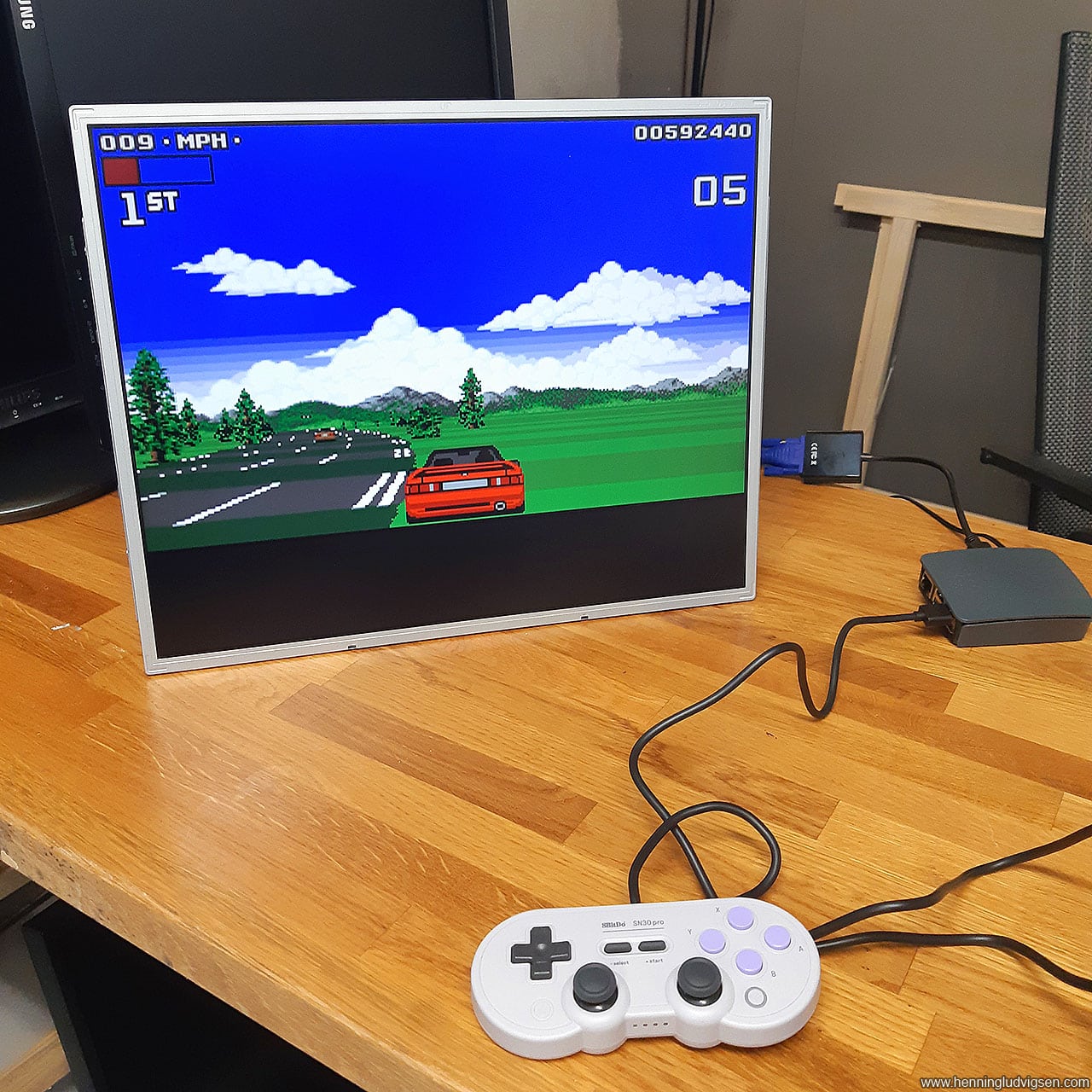
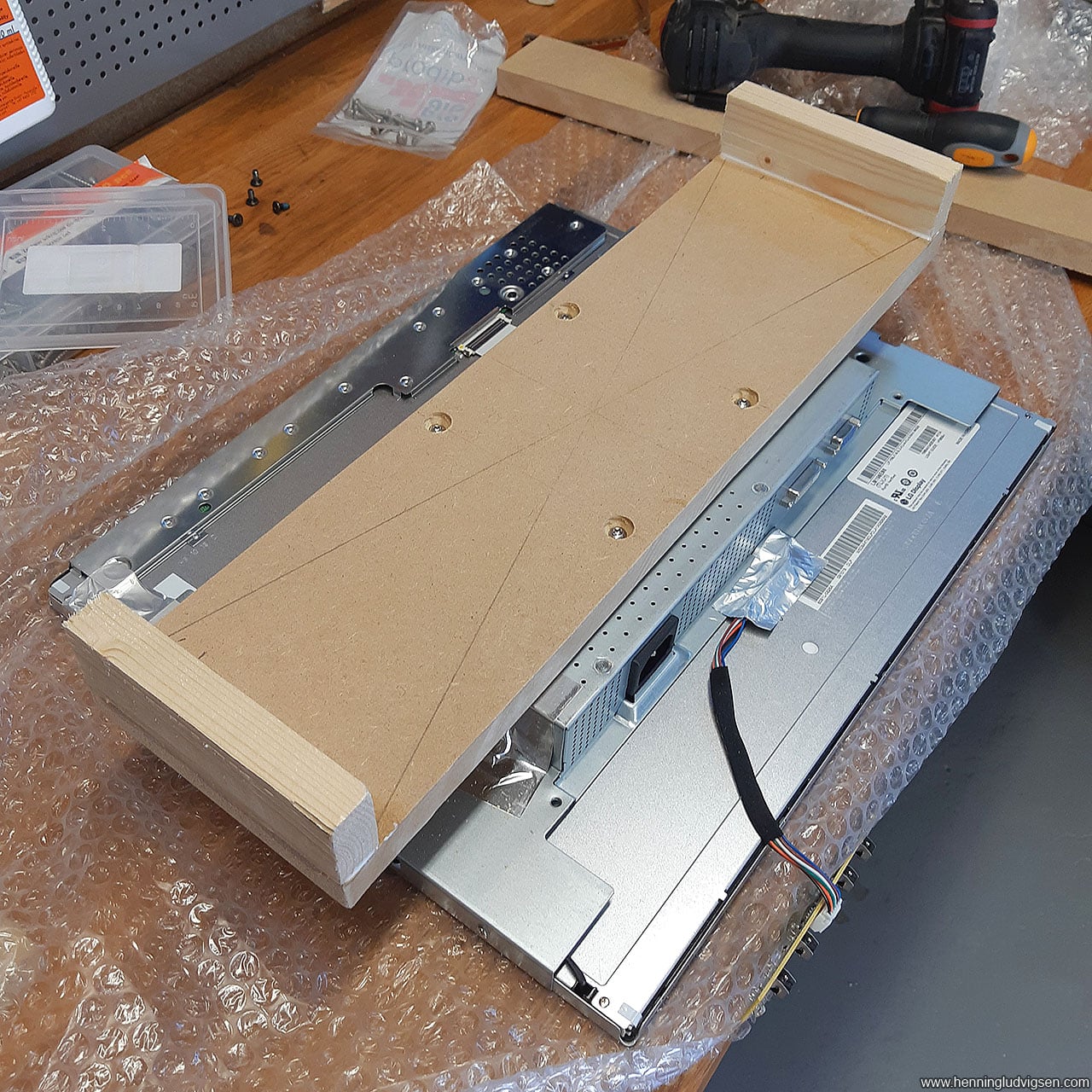
I collected a few older screens, which are easy to get ahold of either for free or for a few bucks, and found a neat 19″ 4:3 screen that I decided to use. I removed the plastic covers and made sure everything works as intended. The PCB with the button panel at the bottom of the screen is lose, and I simply hot-glued it on the back of the screen so that it’s accessible from the back of the inspection door of the cabinet, if needed at a later point.
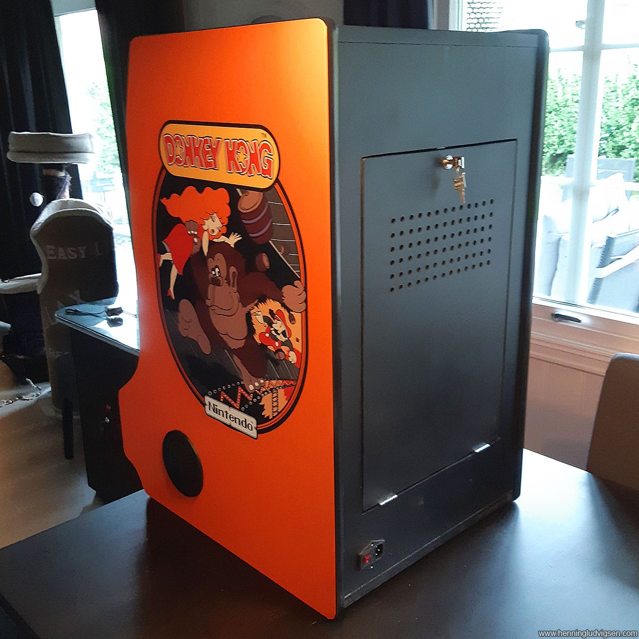
Back wall and inspection door
For the back wall, I measured up the height of the piece from the template and at the width of 47cm as I decided to be a good width earlier in the 3D software visualization.
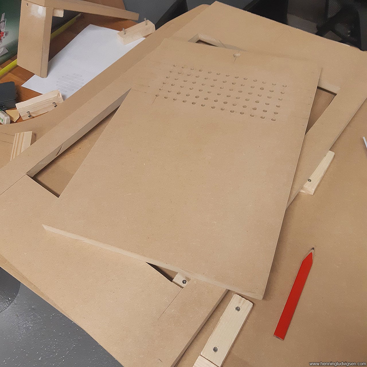
I created the back door by drawing up the lines of the inspection door on the MDF piece and used the circular saw and «dipped» the blade carefully into the wood and cut out the hatch. I had to use a manual saw to cut the edges properly.
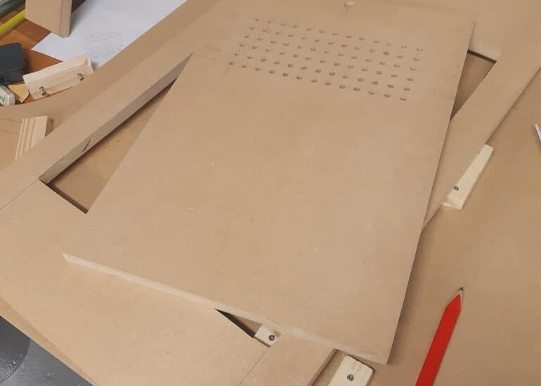
Next drew on a 2×2 cm grid and drilled a bunch of holes for ventilation (Tip: hammer some “guide holes” with a big nail on each of the drill points to guide the drill more accurately). I also used the router to make a hole for the lock. Due to the thickness of the MDF (19mm), I also had to route a slot a few millimetres down into the wood on the backside to make sure the lock sticks through just enough.
Then I sanded the inspection door to make it nice and smooth.
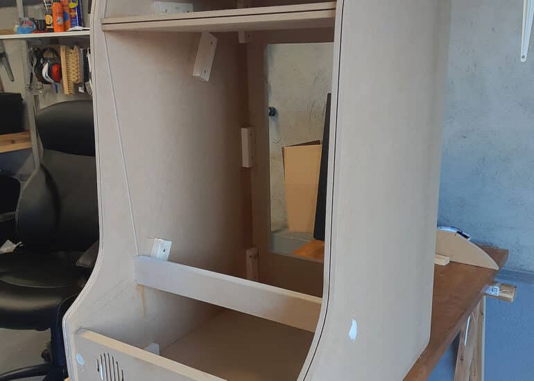
Connection pieces
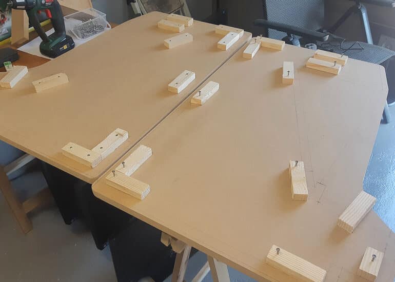
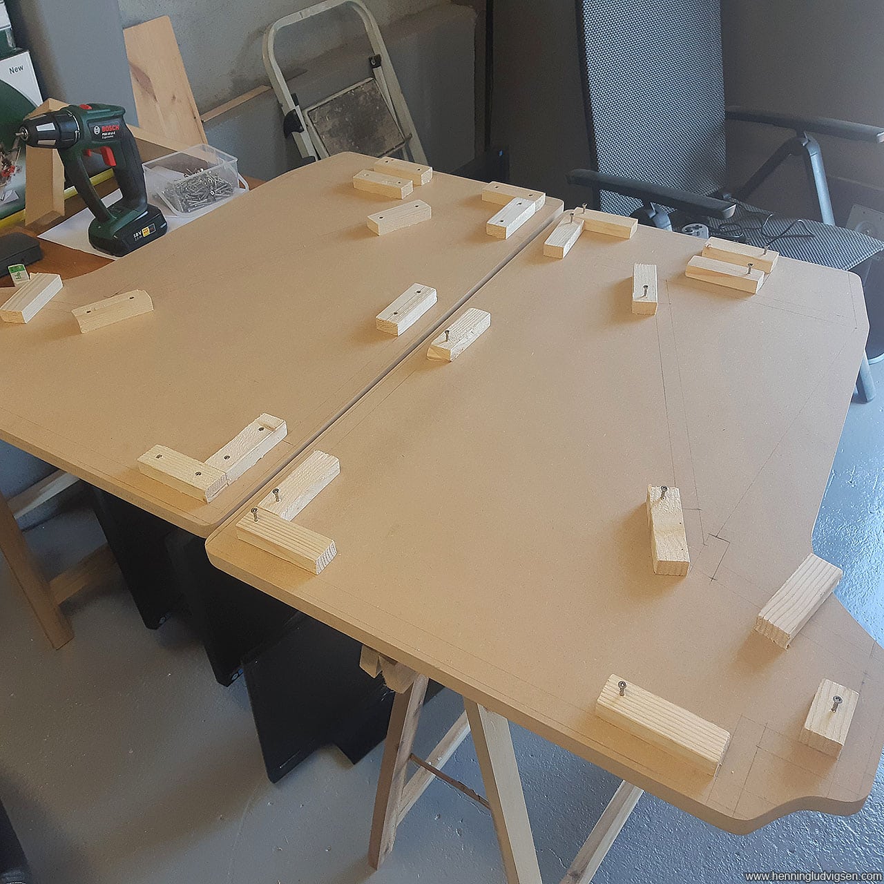
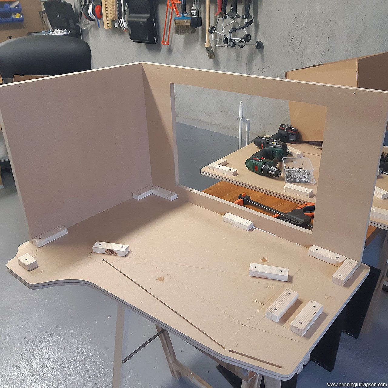
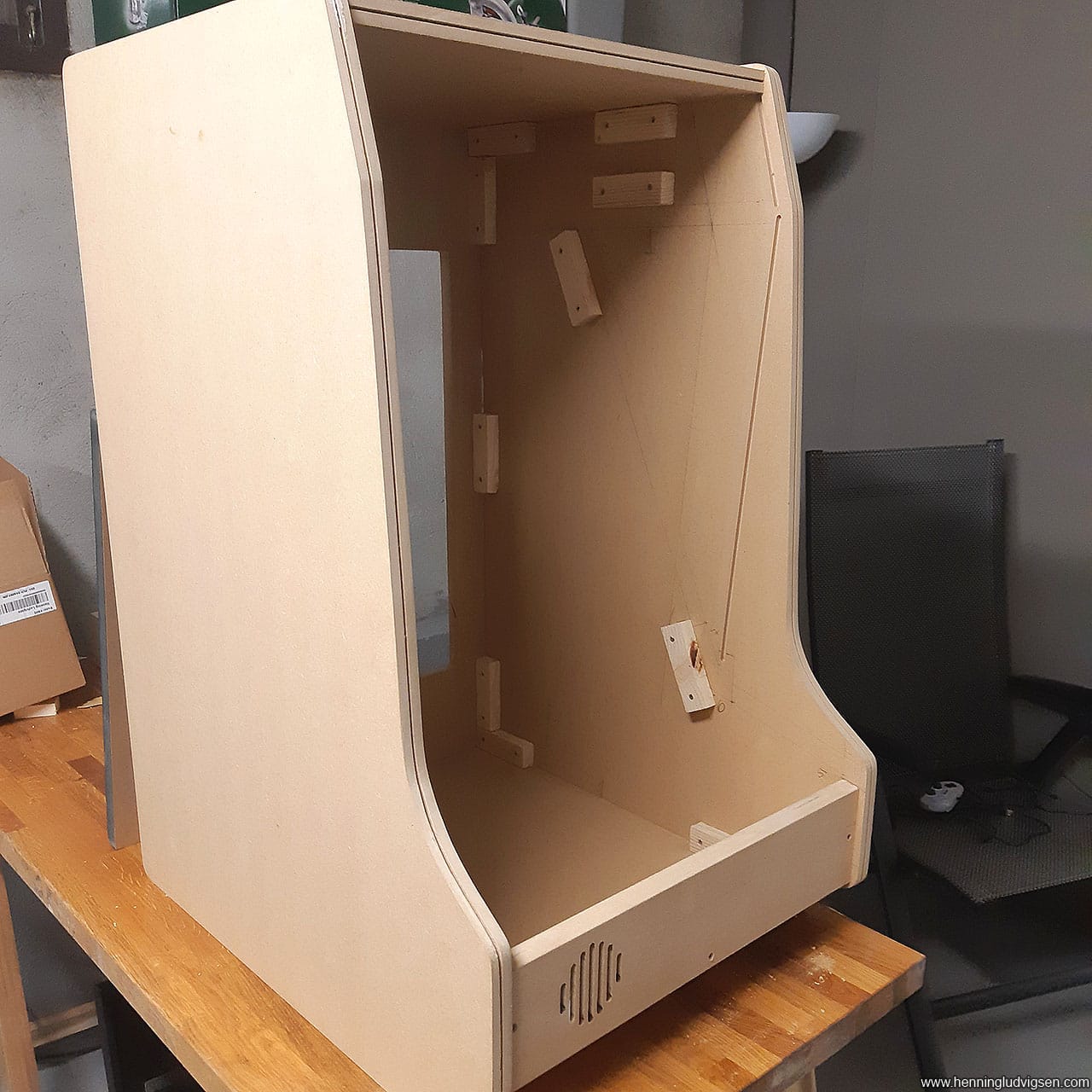
I cut a bunch of small connection pieces out of the thinnest pieces of wood I could find. All at the same length. These will be used to fasten the connection pieces at 47cm between the side walls. Some use them longer, but I don’t see that any longer than this would be necessary.
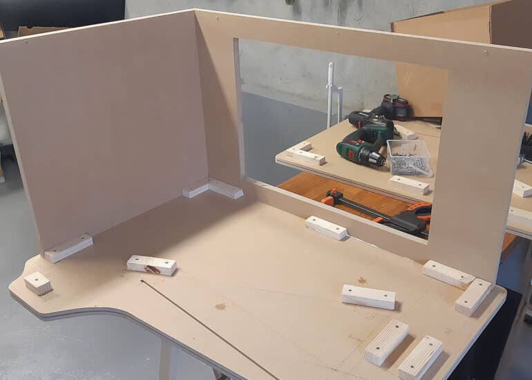
Next, I spent a lot of time drawing up all of the placements of the connection pieces onto the side walls. I had to do a lot of double and triple checking when mirroring the same drawing to the opposite side wall. Be 100% that this is correct before progressing any further!
Next, I fastened all of the connection pieces. I used a thin drill and pre-drilled every hole before adding wood glue and wooden screws. Always pre-drill, it WILL crack if you don’t do this. I used screws that were a little bit shorter than the thickness of the MDF and connection pieces together so that I could attach it from the inside to avoid screw holes on the outside. It’s ok doing it from the outside, but it means more work covering it up with wood filler and sanding later. I also cut all the other MDF pieces that connects the 2 side walls.
Routing
I needed to route slots for the Plexiglas and light box, so I did that next. I made a mistake and had to remove one of the connection pieces to be able to fit the router. Later I also discovered that I made the slots a bit too deep. 1 to 2 mm would have been enough. Argh!
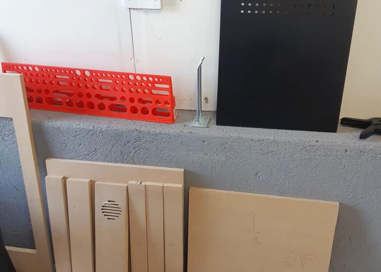
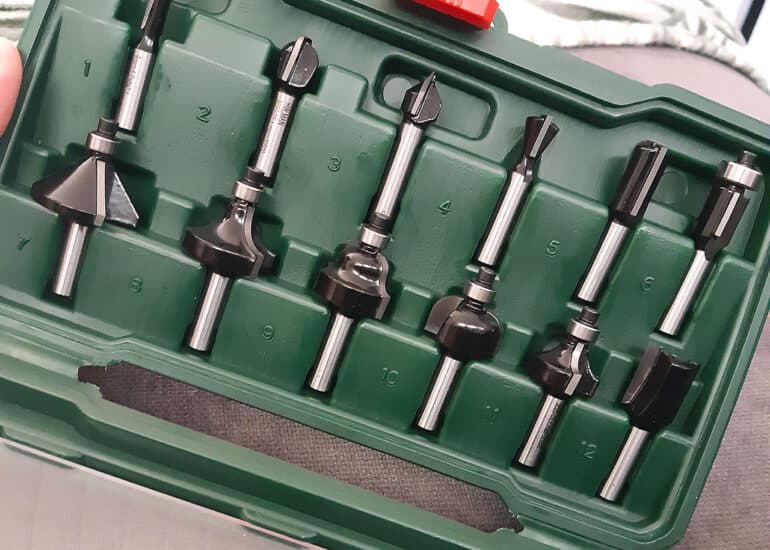
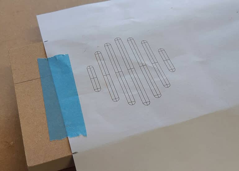
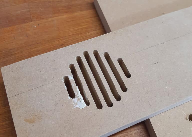
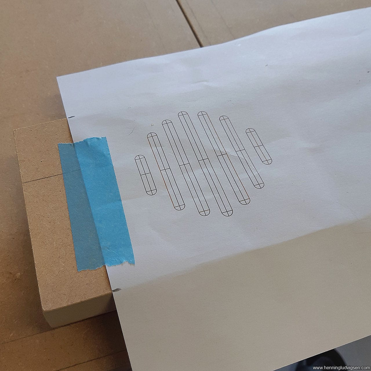
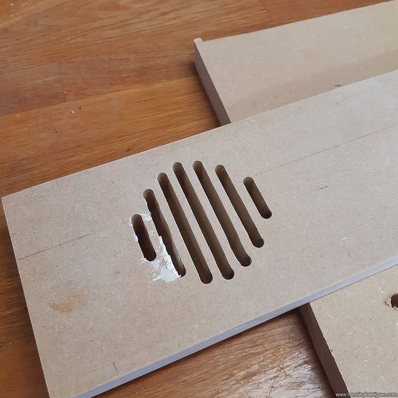
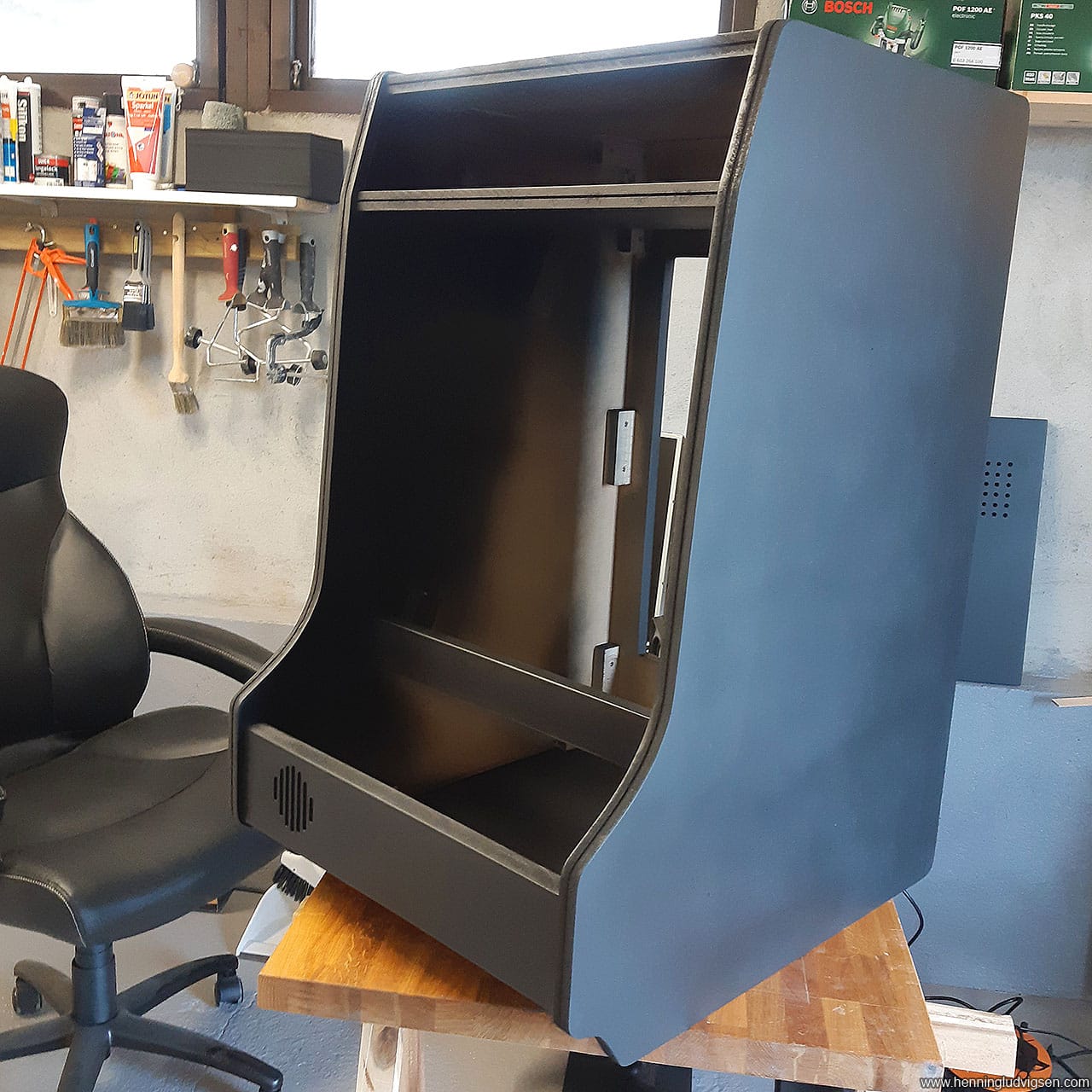
In the same round I also used the router with a slot cutter blade that fits the T-molding I’m using. It’s a good idea to do all the slot cutting before assembling anything. And make sure to fasten the board properly. I was a bit impatient and it moved a bit during my second routing session which made the slots a bit off and wider than they should be. I fixed this before adding the T-molding later, tho’, so it’s not all lost if you make a mistake. Fix with either some hot glue in the trouble areas when adding the T-molding, or make the gap a bit narrower with some wood filler. I also printed out the template for the traditional looking speaker grill found on these cabinets. I taped the template onto the MDF and used a large nail to hammer down the center points of the start and end if each slot. I used the thinnest router head to rout these slots, and I had to clamp a metal ruler for each slot to get each of them nice and straight. One of the slots still got a bit uneven, which I fixed with wood filler and sanding.
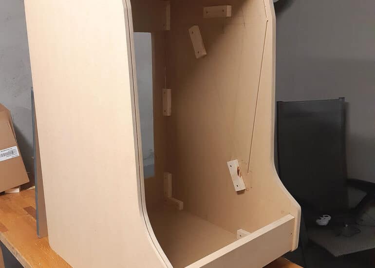
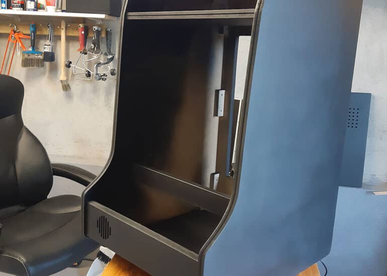
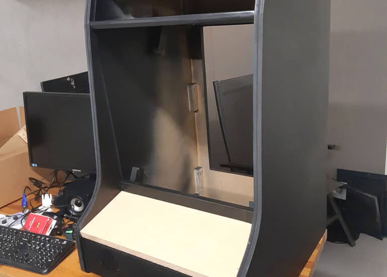
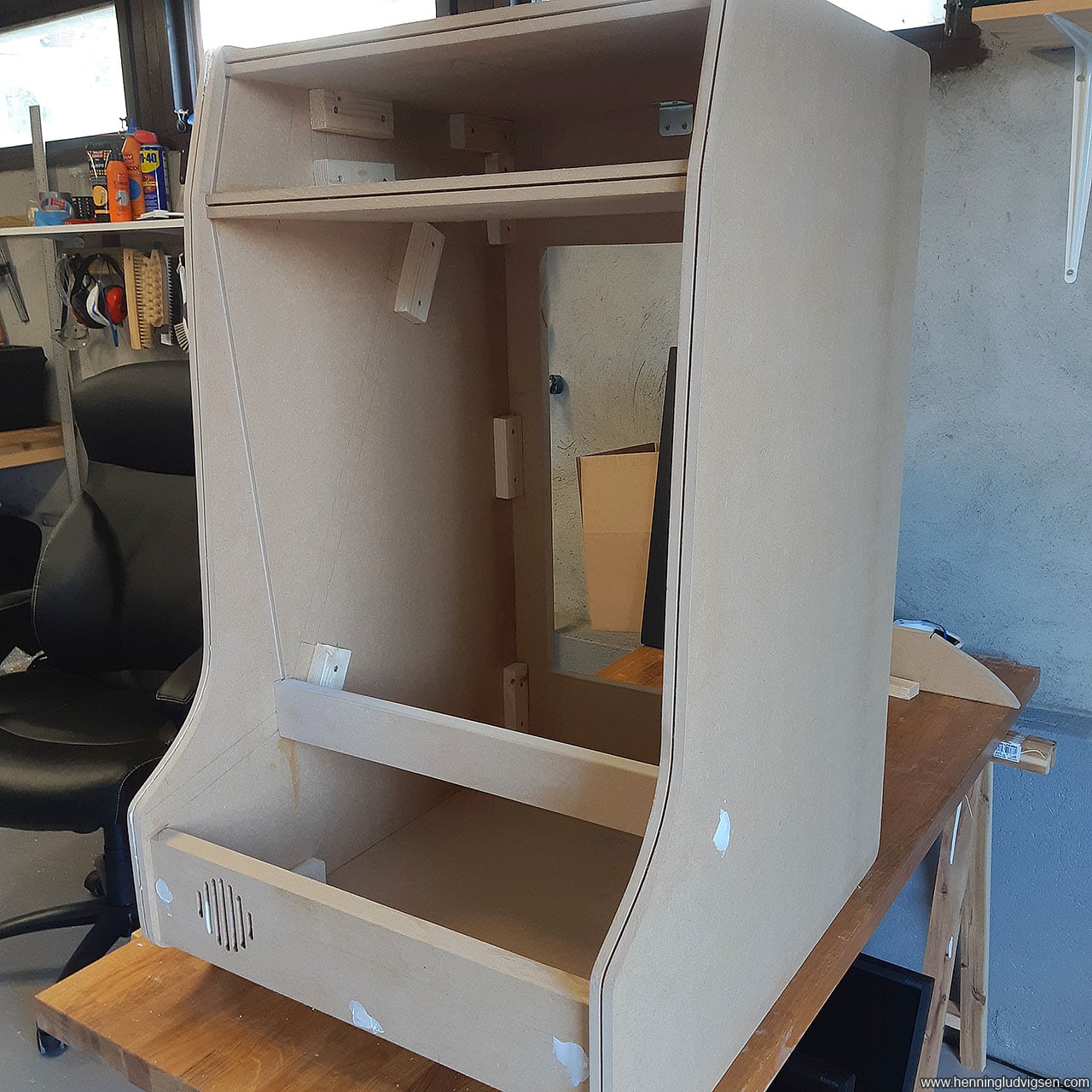
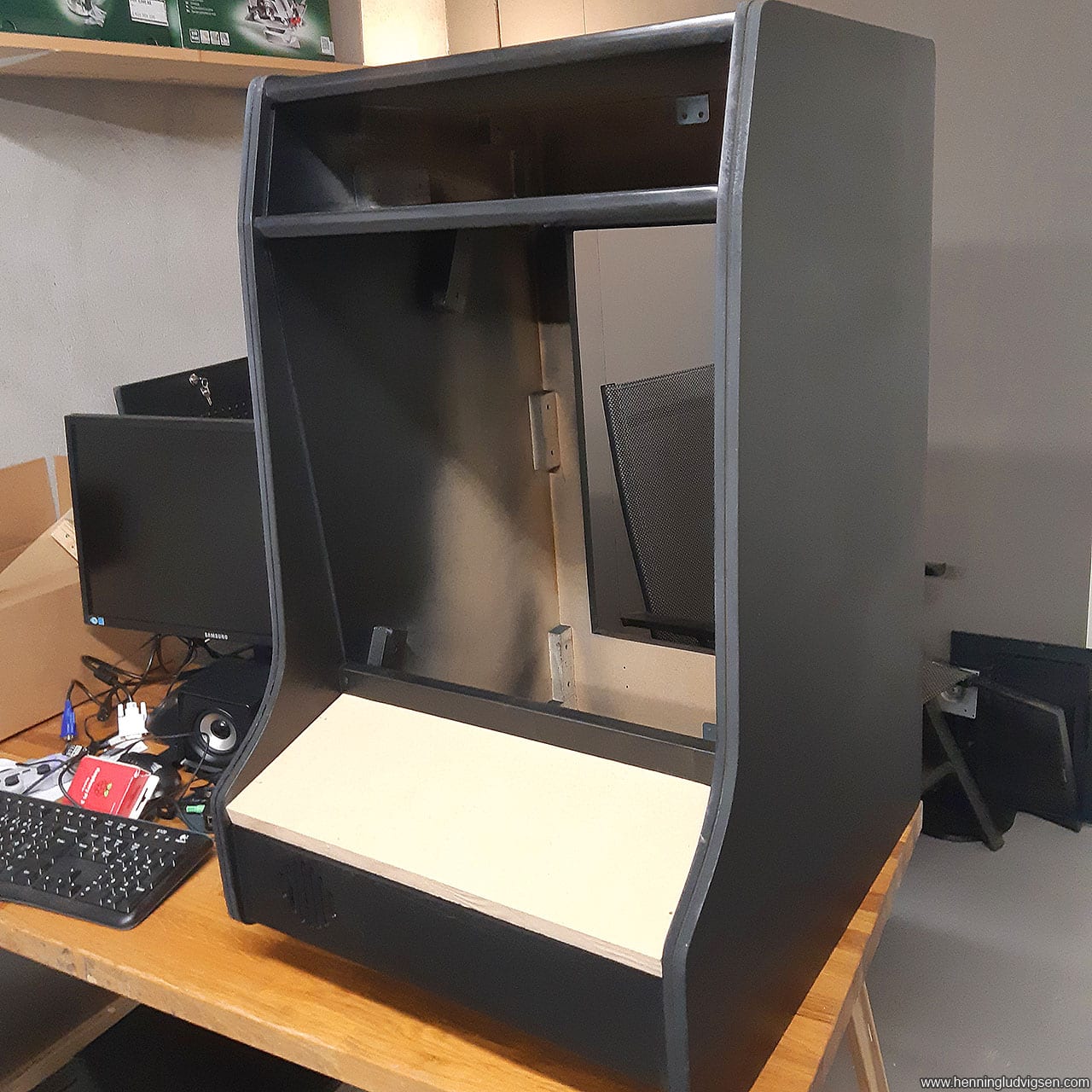
I added the back wall first, as it’s important to maintain the straight angles and structural integrity, and it would lend itself as a good starting point for achieving a good and straight angle. I added glue along the edges and connection areas towards the connection pieces and pre-drilled holes before screwing the piece in place. I made sure to use a countersink drill bit to make sure the screw head is below the surface.
Then I just added the remaining horizontal pieces except for the board for the control panel.
Surfaces
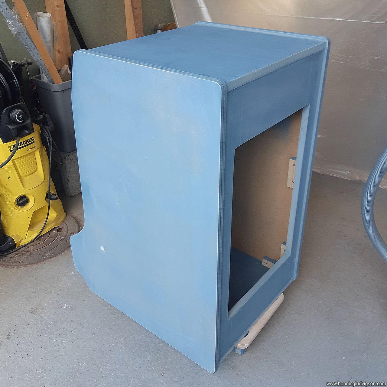
Now for treating the surfaces. After filling all the screw holes with wood filler, I sanded all the surfaces that would be visible or have print on them.
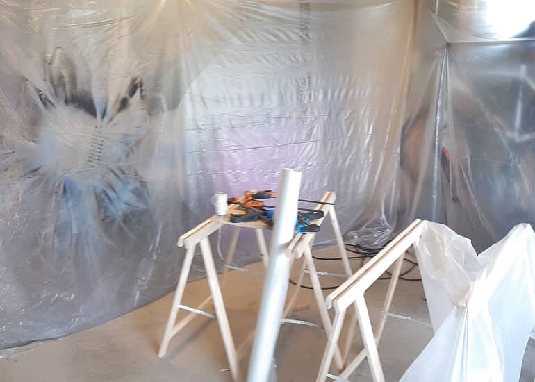
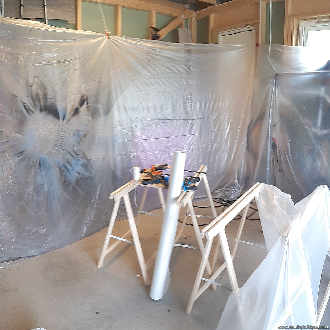
I also built a makeshift spray-booth in my garage. It’s basically just a wall of plastic sheets that can easily be put up and taken down. However, in retrospect I should probably have done the first coats outdoors as I’m sanding it between each coat anyways.
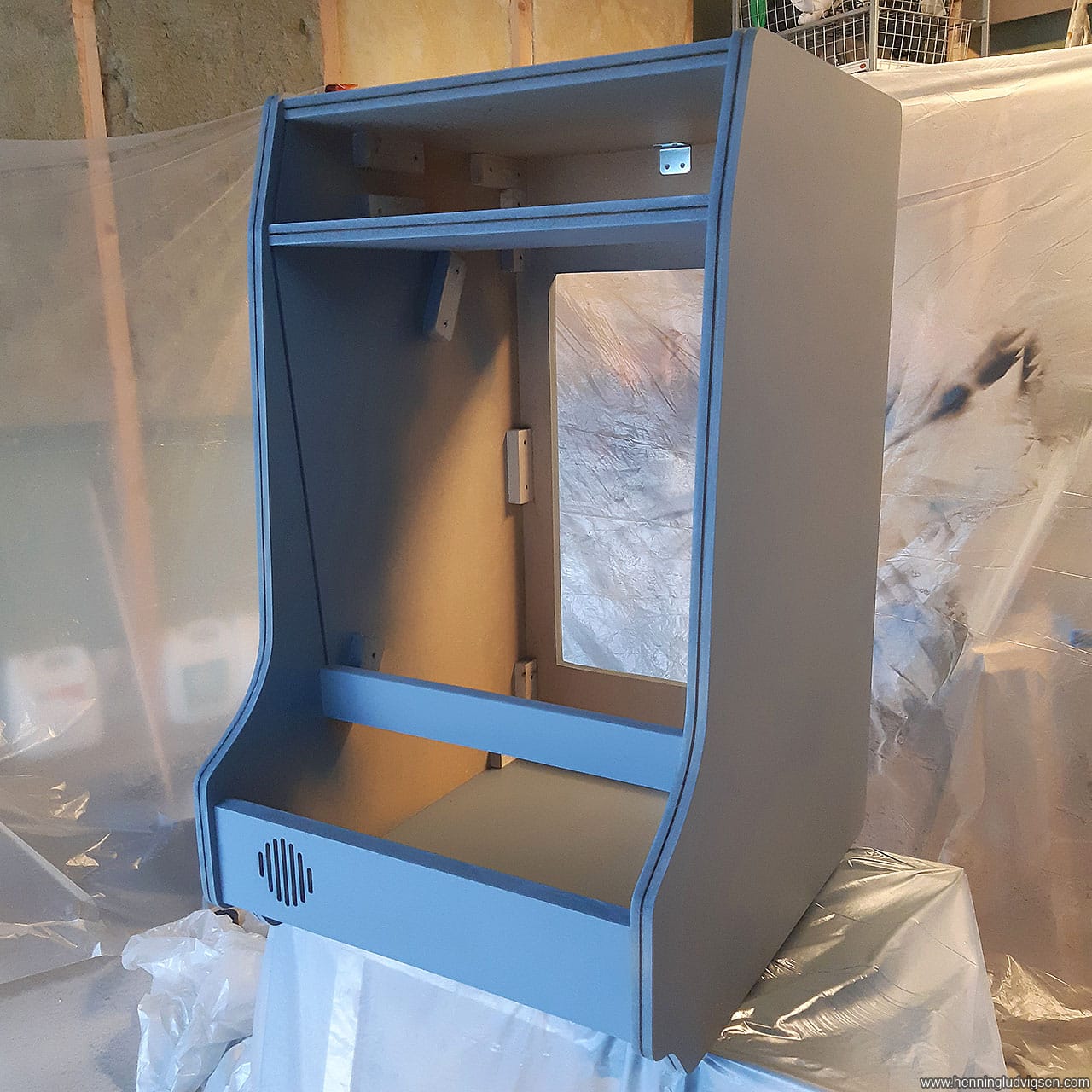
So, first I sprayed a coat with primer, and used a medium grit sandpaper once it had dried.
Then I did the first coat of semi matte spray paint and used a super fine sandpaper once that one had dried.
Then it was time for the final coat which I carefully applied, trying to reach all of the visible areas.
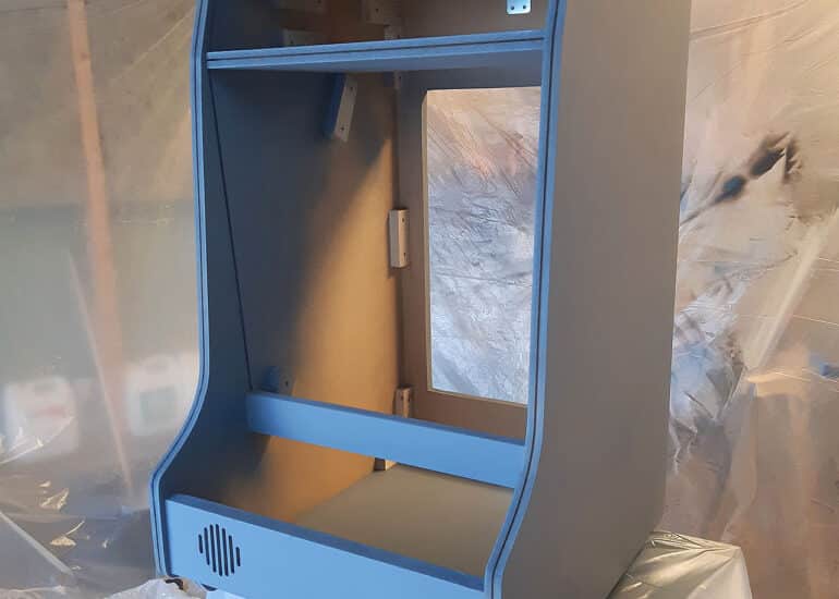
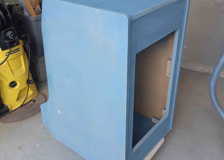
I know I didn’t really HAVE to have this many coats for the areas that will be covered by the print, but this was a test project and I wanted to see how good of a result I could get using spray cans. I was pretty happy with the end result, but I did use a lot of spray. It ended up with 2 cans of primer and 3 cans of black paint. I should be able to half that if done more sparsely.
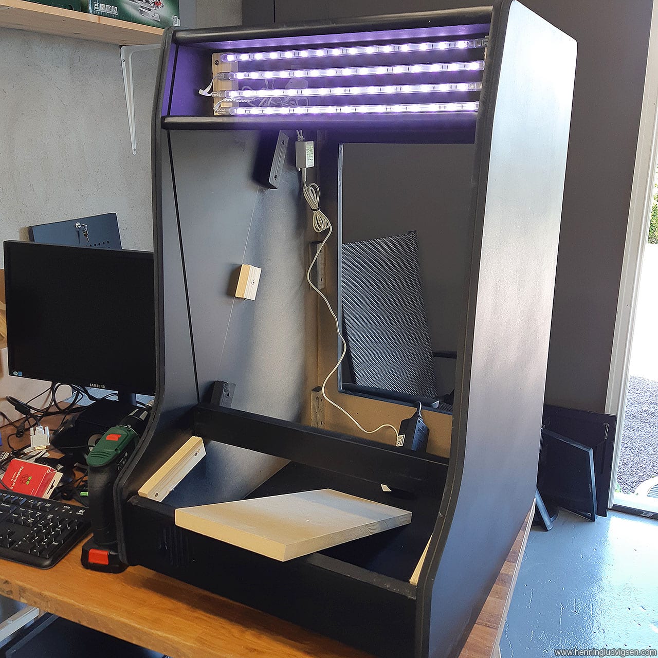
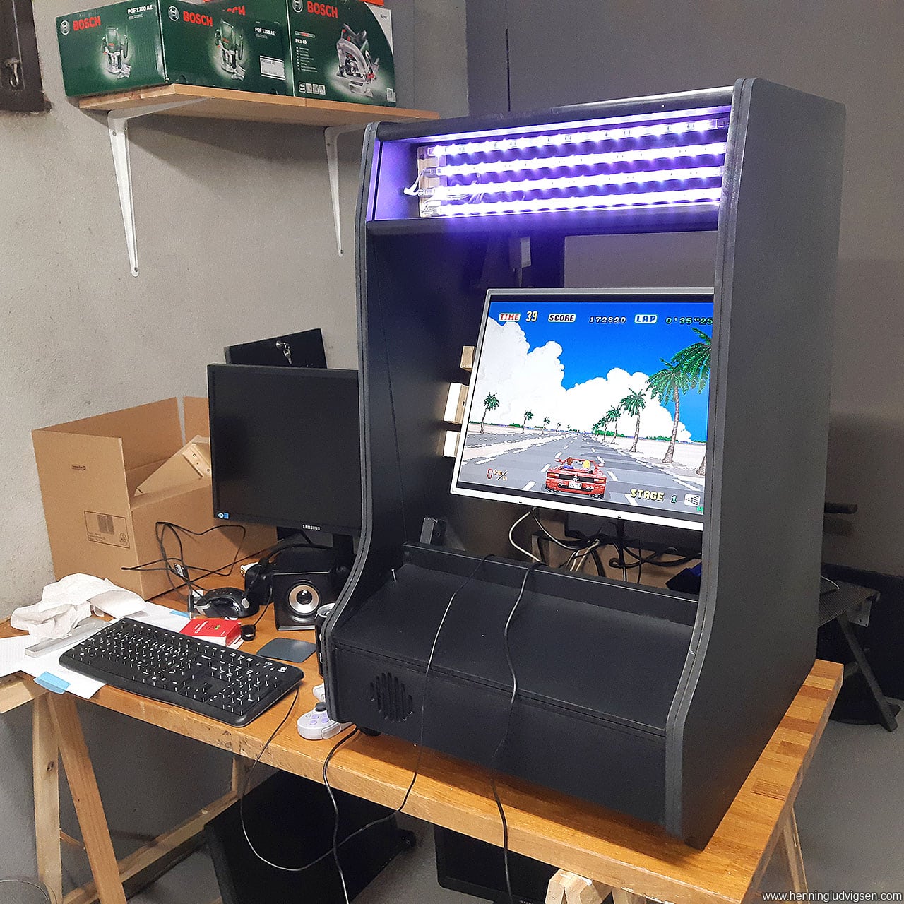
I found some light strips in a drawer that I never used, and added it to the light box at the top of the cabinet.
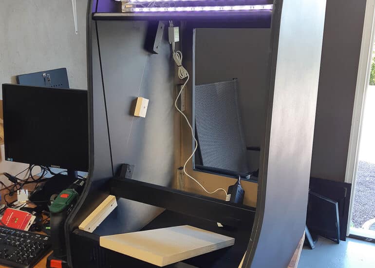
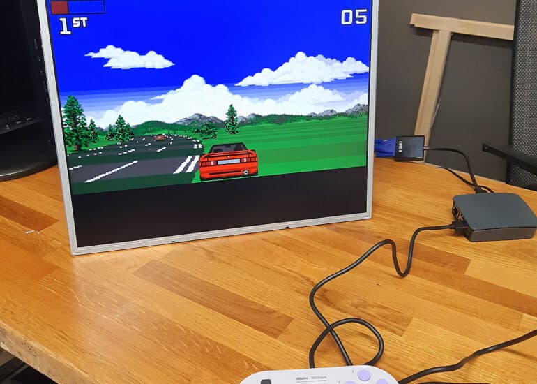
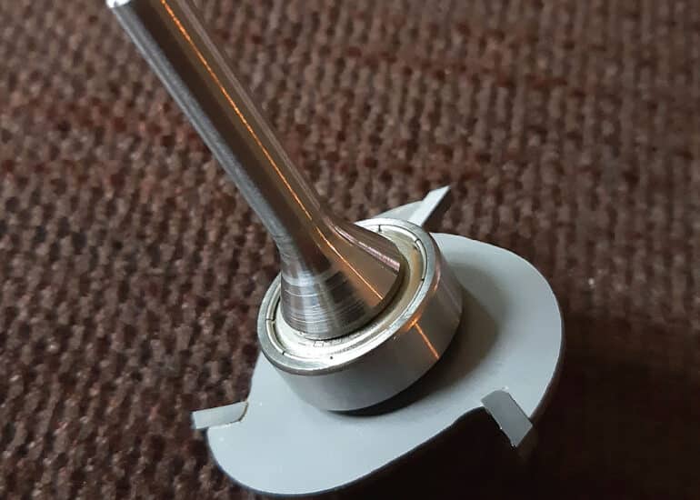
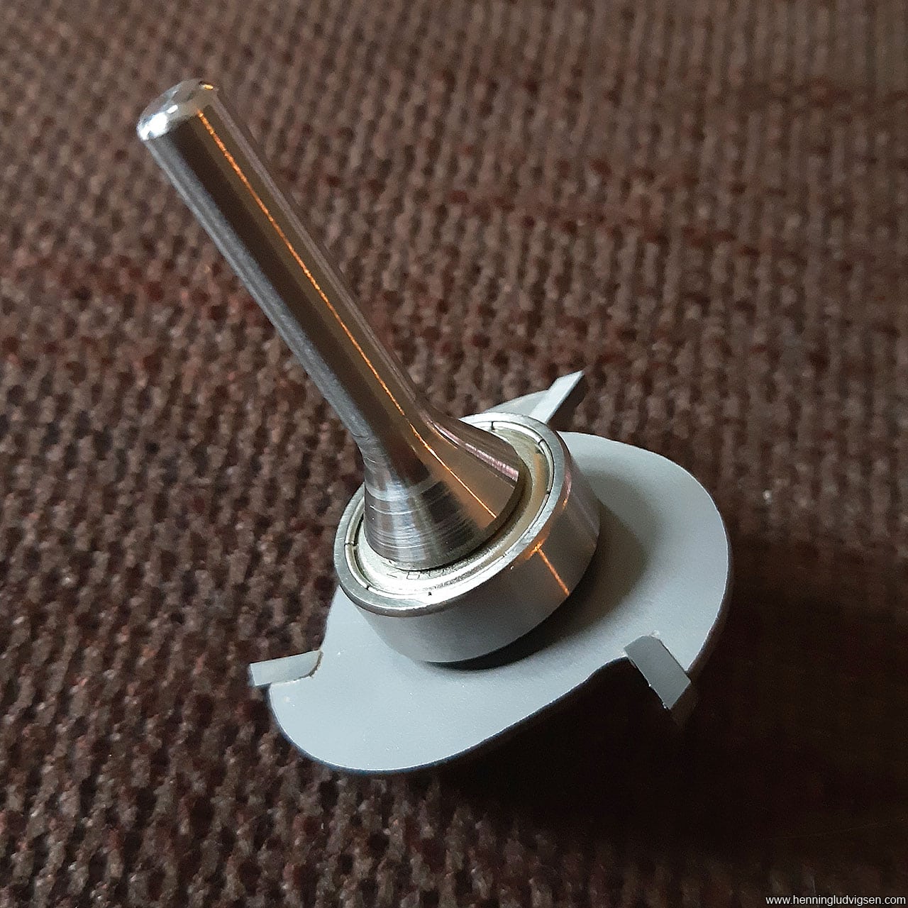
Next I made a simple monitor mount that I mounted onto the monitor with some slightly longer screws. Then I added this to the cabinet in the height that I thought would be suitable.
Plexiglass
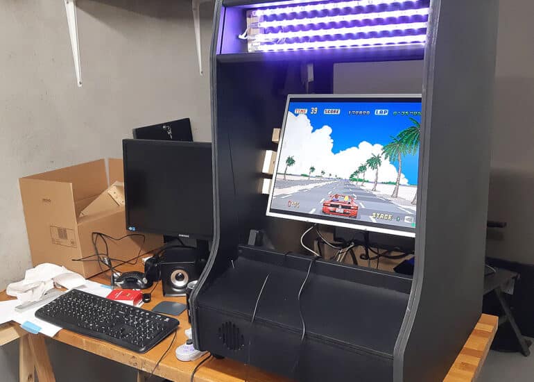
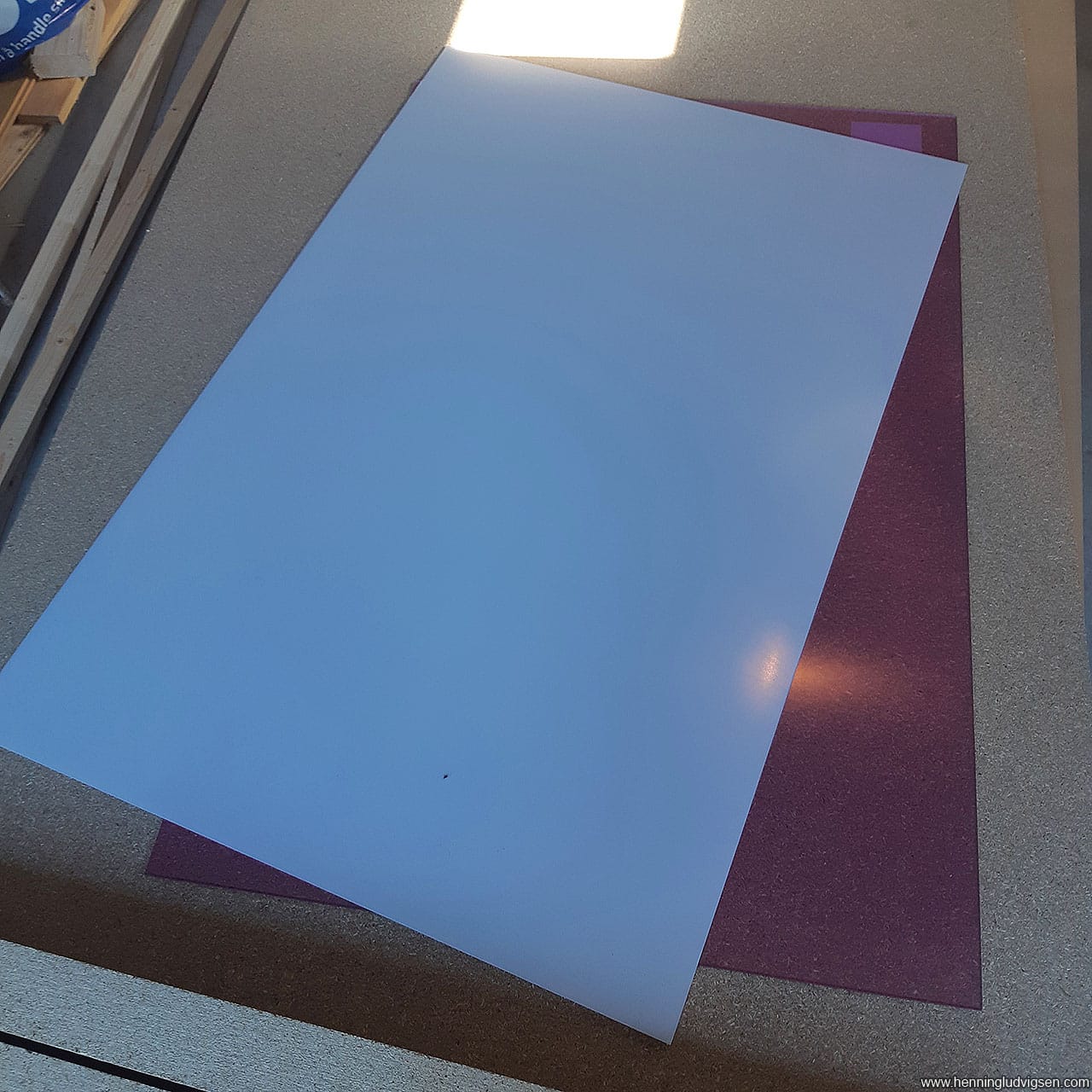
I wanted to have a clean bezel around the screen, so I cut a piece of Plexiglas to fit directly on top of the screen. Since the Nintendo style cabinets have another piece of glass in front, I didn’t want another sheet of glass covering the screens, so I marked there the screen was located on the glass and cut out a square.
At this moment I still had the protective film on the glass, so after sanding the sides I removed the protective film on one side and spray painted it with a thick coat of paint, and mounted it into the cabinet with the paint on the backside. This way the surface looks super clean and neat!
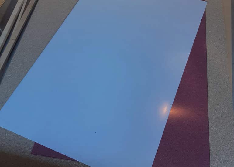
As I don’t have any experience cutting Plexiglas I tried a few different methods. I’ve seen people use clamped rulers to use as a guide with the jigsaws, but that didn’t work at all for me. The blade kept bending and creating wavy end results. I ended up cutting completely by hand and then sanding down any uneven lines.
Towards the end I used the method of clamping down a big metal ruler and cutting multiple times with a carpet knife before breaking it along the edge of the table. This is definitely what gave me the best result. I also learned that it’s best to keep the piece you want to use on the table and break off the excess Plexiglas.
Control panel
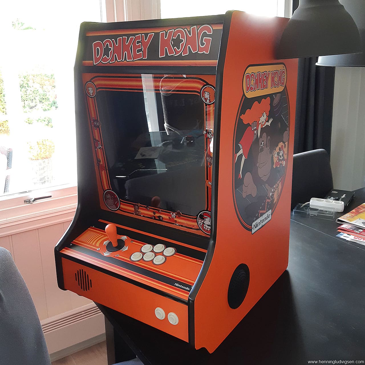
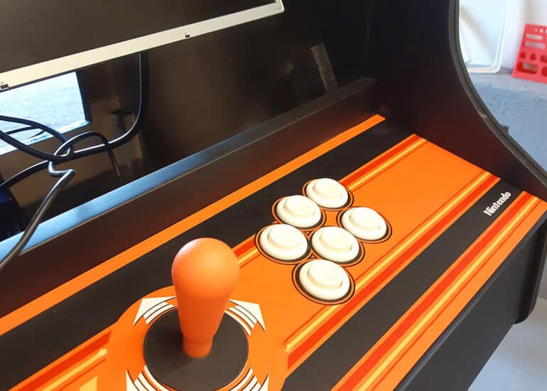
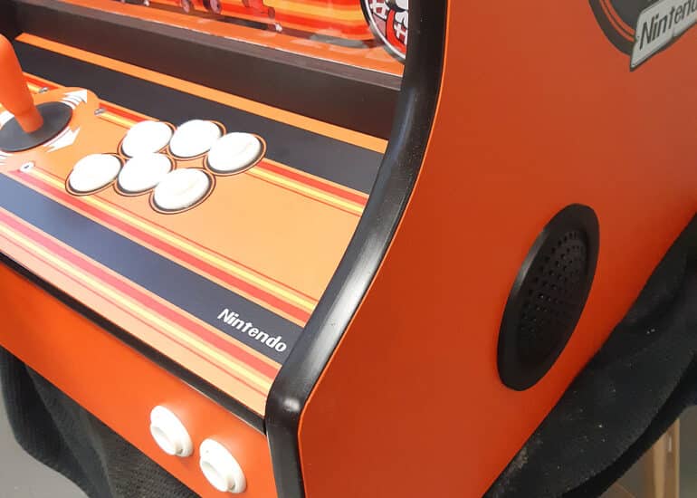
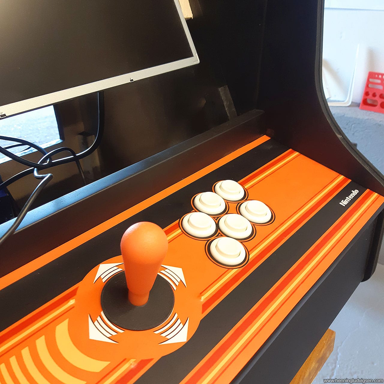
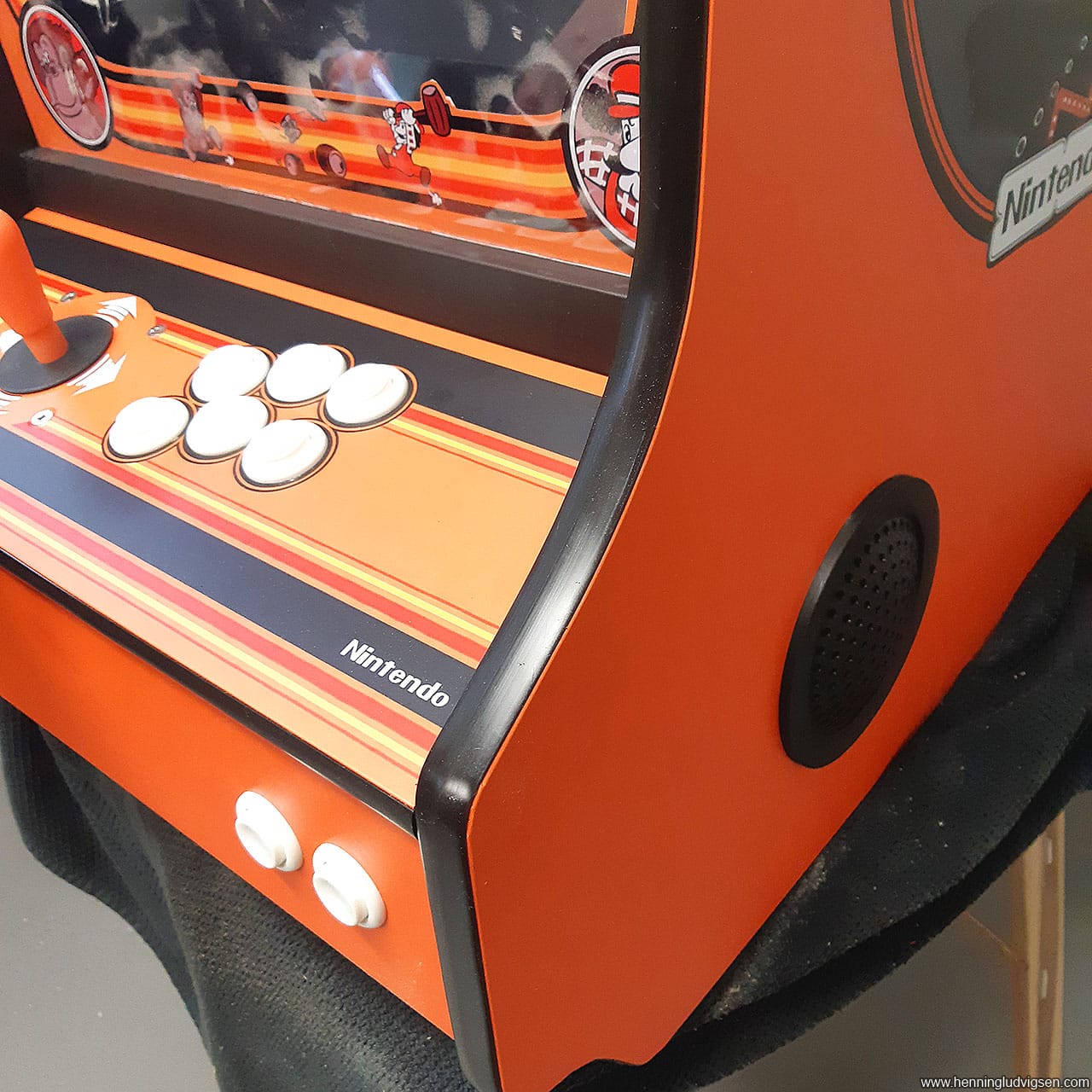
After sanding and painting the control panel with a couple of coats, I applied the decals. The decals contain cross-hairs for the center of the placement of the joystick and buttons, and I drilled the holes after and installed the joystick and buttons.
Decals and wrapping up
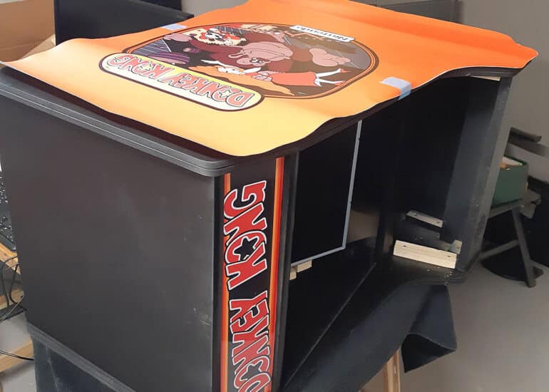
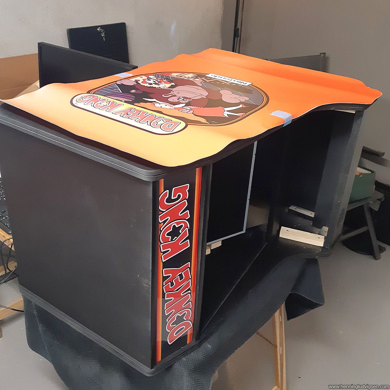
Next I added the decals on the sides. To make sure it gets straight I laid the cabinet on its side and placed the decal loosely on top and taped it in the center on both sides to make sure it’s not going anywhere. Then I lifted one side of the print, removed the backside of the sticker and cut off the protective paper. Next I used a squeegee to apply the sticker slowly from the center where the tape is and out towards the edge making sure there are no air bubbles underneath the decal.
Next I removed the protective sticker on the opposite side and applied the second half the same way.
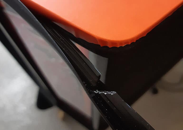
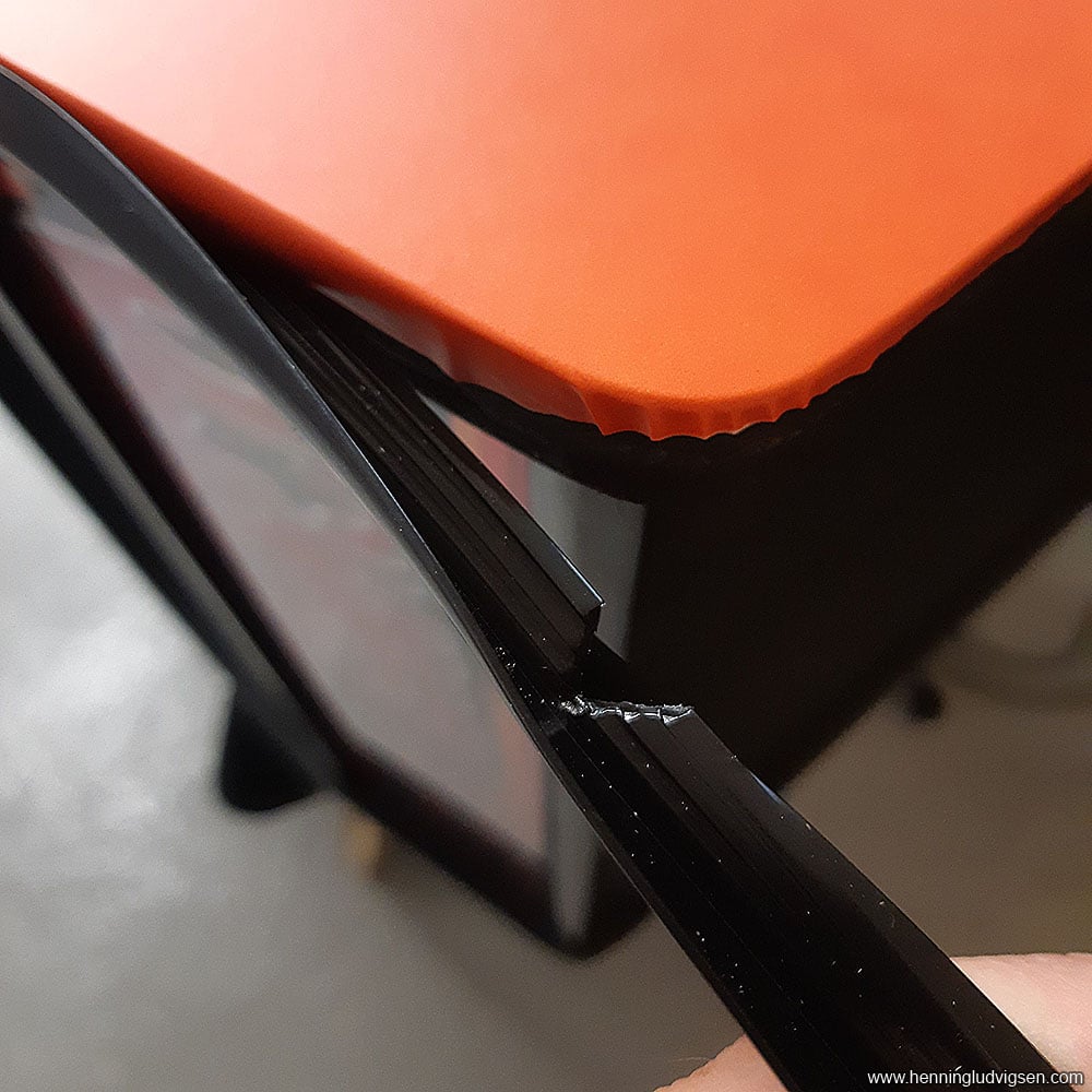
The T-molding gets applied by carefully hammering it down with a soft rubber mallet. Make sure to cut off wedges of the lip that goes into the slot in the edges of the cabinet.
I also applied the plain orange decal on the front bottom. It was a bit fiddly cutting out the speaker hole with a razor knife.
I also applied the bezel decal on the glass. This decal has the glue on the printed side to be able to go on the inside of the glass. This one was a bit fiddly due to the hole inside and that it was hard to match it up without any folds. Next time I will use soap water to apply the decal on the glass. By spraying on water with dishwater you can quite easily move the sticker around without the glue sticking. Then when you’ve got the perfect placement use a squeegee to push out all soap water and air bubbles and it will stick properly.
Applying the glass was a bit of a hassle as I made the slots on the sides a bit too deep, which led the glass to fall out on its own. I solved this by screwing in 2 tiny screws in each slot to make them less shallow. Once it’s popped in, it will be a hassle to remove, so make sure there’s no dust or unfinished business behind the glass.
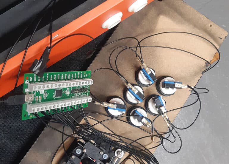
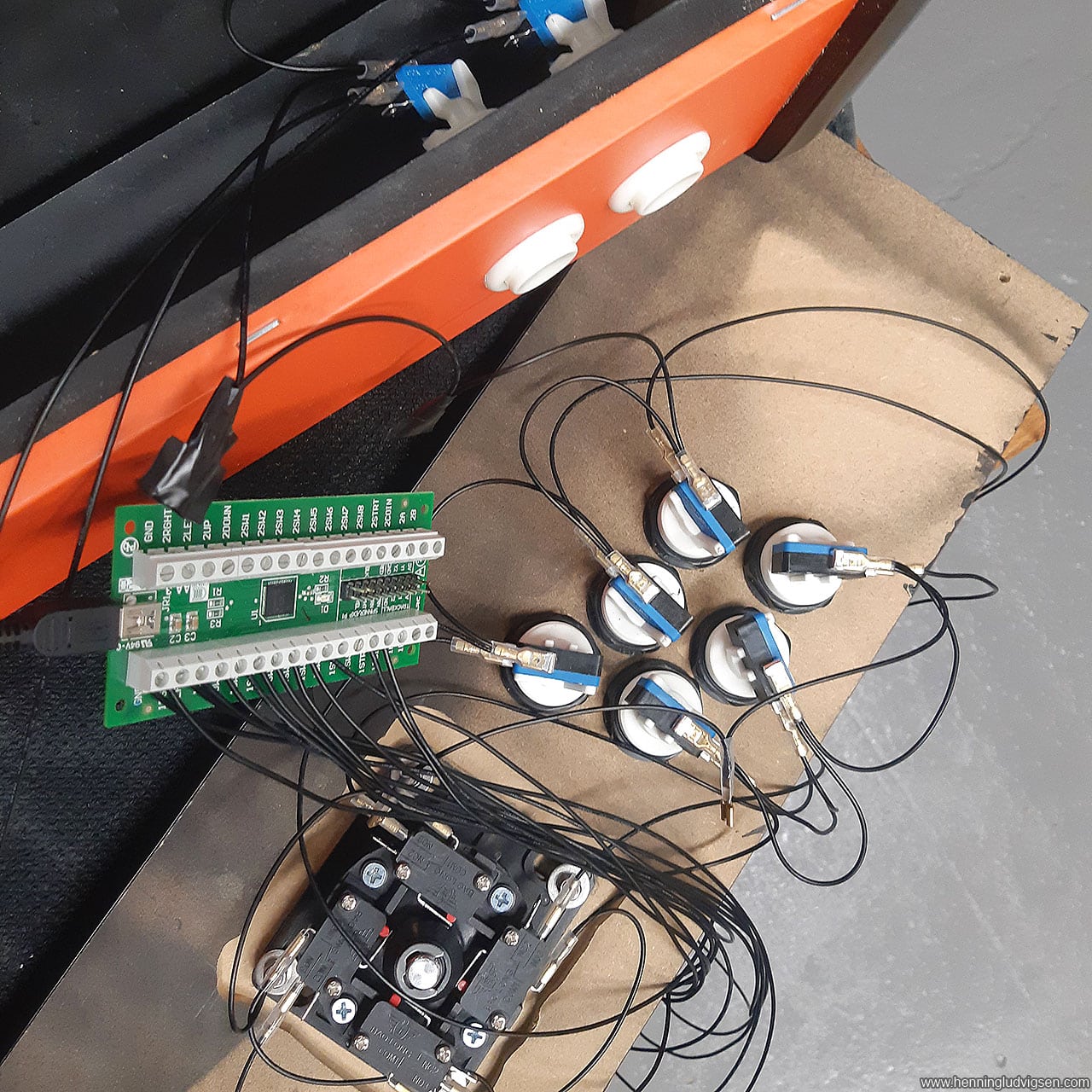
Lastly, I connected the controller and buttons to the controller board, mounted the controller board and fastened the control panel. I decided to mount the control panel with 4 screws to be able to easily be able to open it up in case of need for repairs or changes.
I’m using a I-PAC2 controller interface board from Ultimarc. This board is set up to work as a keyboard out of the box and I was struggling making it work properly with the different emulators. Turns out it has 5 modes. By switching to Mode 2 (Dinput Preset) it will act as unique USB controllers, which works perfectly! To switch to this mode press and hold Start1 and SW2 simultaneously for about 8 seconds until you see the LED light on the controller interface blink.
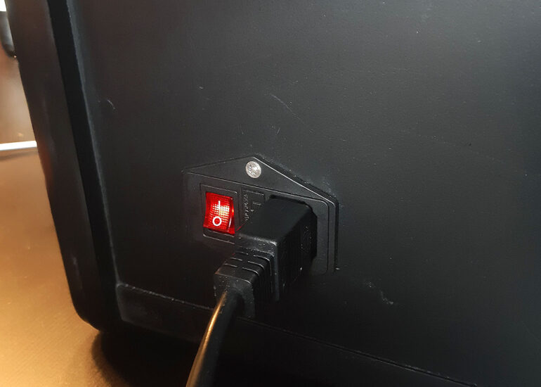
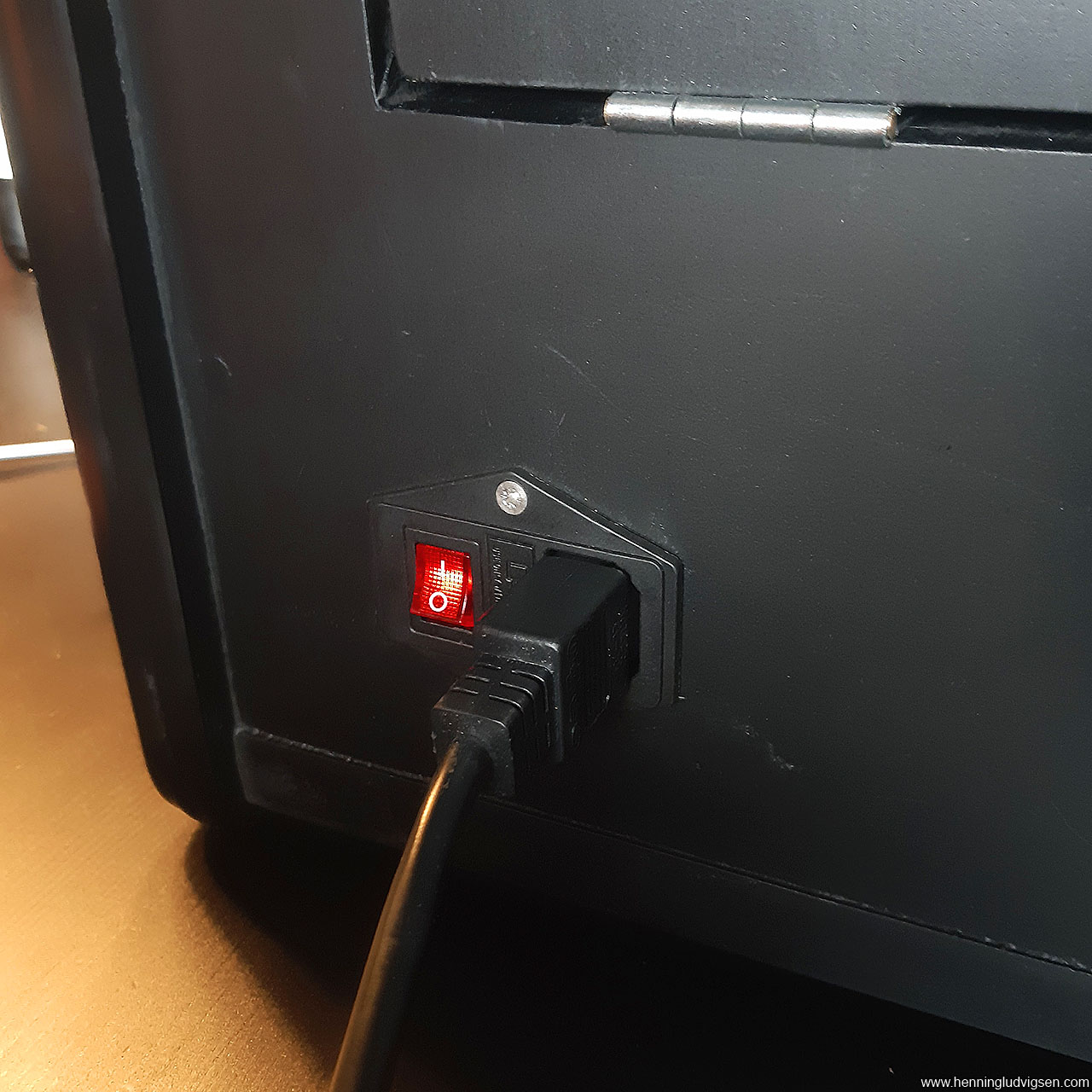
Lastly I mounted the Raspberry Pi 3b+ to the side of the wall, drilled speaker holes on each side, added speaker covers, and hot glued the speakers in place on the inside. I placed the base of the speaker behind the man made speaker grills in the front of the cabinet. I also drilled a hole in the back for this neat power switch, which I got help to solder on the inside. That thing makes it feel a lot more professional and neat!
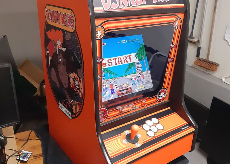
…and that’s it!
I got most of the arcade-related parts for www.arcadeworlduk.com
Tools list:
- Circular saw with fine toothed blade
- Jigsaw with fine toothed blade
- Drills
- Countersink drill bit
- Large metal ruler
- Clamps
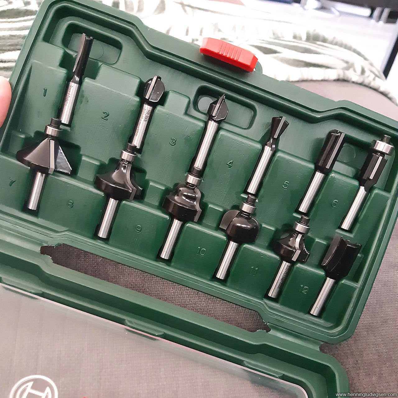
- Router
- Slotting cutter arbor
- Slot cutter blade for 19mm T-molding
- Angle ruler
- Measuring tape
- Rubber mallet
- Sanding machine
- Stanley knife
- Wood glue
Parts list:
- 19mm MDF
- Thin wood pieces
- Raspberry pi 3b+
- 19mm T-molding
- 2 different types of plexiglass
- HDMI to VGA connector
- Old-ish 3:4 screen
- Classic concave plunger buttons with Chen Xiao Button Microswitch With 4.8mm Terminals
- AWUK Competition joystick
- I-PAC 2 and wiring kit
- Standard LED strips
- Cheap stereo from BILTEMA
- Basic power cord with more than 4 outlets
- On/Off 240V Inlet Socket switch
- PCB Feet
- Primer spray cans
- Quick Bengalack spray paint
- Screws
- Hinges
- Lock
- Vinyl print
- Speaker covers
Plans for download:
Please note that some tweaks were done during the building process. For instance the connection pieces that are displayed as covering whole lengths in the blueprint was overkill, so I only made short pieces that I attached where needed. But the overall side shape and placements are good as a starting point.
That is really great do you mind me building one like that? Do you have the dimensions somewhere of the wood? Because the blueprint does not show the dimensions!
Hello, thanks for your comment! I don’t have the measures noted down. The blueprint is in 1:1 scale, so you should be able to measure from the image. Good luck!